
Specifications


SSG 500-series Installation and Configuration Guide
14 Back Panel
To transfer data between a USB storage device and an SSG 500-series device:
1. Connect the USB storage device to either the upper or lower USB port on the
security device.
2. Save the files from the USB storage device to the internal flash storage on the
device with the save {software | config | image-key} from usb filename to
flash command.
3. Stop the USB port with the exec usb-device stop command before removing
the USB storage device.
4. Remove the USB storage device.
If you want to delete a file from the USB storage device, use the delete file
usb:/filename command.
If you want to view the saved file information on the USB storage device and
internal flash storage, use the get file command.
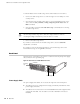
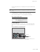
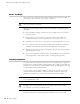
Back Panel
The back panel of an SSG 500-series device contains the fan tray and power supply
unit(s) and a two-hole grounding lug.
Figure 4: Back Panel of an SSG 500-series Device
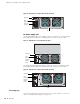
Power Supply Units
The power supply units (PSUs) are located at the right side of the back panel:
The SSG 520 device is equipped with a single permanently installed AC or DC
power supply unit (PSU).
The SSG 550 device has slots for two field-installable PSUs and is supplied with
a single AC or DC PSU. You can add a second AC or DC PSU for increased
reliability.
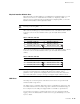
CAUTION: Always execute the exec usb-device stop command before
disconnecting a USB storage device. Disconnecting a USB device without
executing the stop command may cause the device to restart.
Grounding
lugs
Power Supply Units