
User Manual

ENFORCER Component Video Baluns
2 SECO-LARM U.S.A., Inc.
Features:
• Send component video and digital audio
signals over a single Cat5e/6 cable
• Wall or desktop versions available
• Passive operation: No power required
Specifications:
Overview:
• Gold-plated RCA connectors
• Programmable digital audio or IR transmission
• Supports HDTV signals up to 1080p
• Single RJ-45 output connector
Auido / Video
Max. range
1080p 160’ (50m)
480i 1,000’ (300m)
A
udio 900’ (280m)
Video format YPbPr or RGB (1080p/1080i/720p/720i/480p/480i)
Maximum input 1Vp~p
Insertion loss
Audio
Less than 1.5 dB over the frequency range
Video 0.8 dB for 0.1 MHz. increases to 4.0 dB over the frequency range
Return loss
A
udio Greater than 14 dB over the frequency range
Video Greater than 14 dB over the frequency range
Common mode rejection -60 dB maximum
Bandwidth
A
udio 60 MHz, 4 dB roll off
Video 25 MHz, 1.5 dB roll off
Power No power required
Connections
Wire type UTP (unshielded twisted pair)
Wire category
20 - 24 AWG @ screwless terminal blocks
CAT5e or CAT6 for improved range
Connectors
Input RC
A
/ Terminal bloc
k
Output RJ-45 See pin configuration on page 3
A
ttenuation DC ~ 5 Mhz, 1.5 dB max
Other
Dimensions
Wall-plate 4
1
/
2
" x 2
7
/
8
" x 1
5
/
8
" (115 x 73
x 41 mm) without plate
Standard 3" x 2
5
/
8
" x 1" (76 x 67 x 25mm)
Weight
Wall-plate 3.4 oz
Standard 5.0 oz
Humidity range 0 ~ 95%
Temperature Range 14°~165°F (-10°~74°C)
Case
Wall-plate PC plastic
Standard
A
luminum
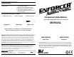
RCA video
connectors
RJ-45 connector
IR terminal block
RCA audio
connectors
MVE-PC015Q
MVE-PW015Q
RCA video
connectors
RJ-45 connector
RCA audio
connectors
IR terminal block
IR / digital audio
switch
G
B
R
A
(Back)
(Front)
ENFORCER Compnent Video Baluns
SECO-LARM U.S.A., Inc 3
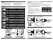
1. Mount and install the baluns where the video inputs and outputs can be easily accessed.
2. If using the included mounting plate, attach the plate to the balun using the included screws.
3. Connect the Cat5e/6 cable to the RJ-45 outputs on
the back of both baluns. Use T568B wiring
standard.
4. Determine whether audio transmission or IR
transmission will be used, and set the Audio/IR
switch accordingly. See Sample Application 1 & 2.
5. Connect the male RCA plugs to the female RCA
inputs on the baluns.
6. If using IR transmission, connect the IR signal using
the terminal blocks on the balun.
Sample Application #1: Using Audio Transmission
Up to 590’ (180m)
MVE-PW015Q
MVE-PC015Q
MVE-PC015Q
MVE-PW015Q
Installation:
NOTE: The com
p
onent video baluns MUST be used in
p
airs.
Sample Application #2: Using IR Transmission
Component
video source
Up to 590’ (180m)
Component
video source
Amplifier
or
or
IR/Audio switch
set to Audio
MVE-PW015Q
MVE-PC015Q
or
MVE-PC015Q
MVE-PW015Q
or
IR control
module and
IR sensor
IR emitter
RJ-45 Pin Configuration
IR/Audio switch
set to IR
Connector Pins
Red (Pr) Pins 7 & 8
Green (Y) Pins 3 & 6
Blue (Pb) Pins 1 & 2
Digital audio or IR Pins 4 & 5
Use T568B wiring standard
NOTE: Baluns MUST be used in pairs.
NOTE: Baluns MUST be used in pairs.