
Installation Manual


ENFORCER 33ft Polarized Reflective Photoelectric Beam Sensor
2 SECO-LARM U.S.A., Inc.
Specifications:
Model
E
-
931
-
S
33P
R
G
Q
Type
Polarized r
eflective
photoelectric beam sensor
Sensing range
33
ft (1
0
m)
Operating voltage
12
-
30V DC/AC 60Hz, 100mA
Current drain
Standby
55mA@12VDC
Active
40
mA@12VDC
Response time
10ms
(max.)
Light source
IR LED
/Wavelength 740nm
LEDs
Solid
Green
Good beam signal, properly aligned
Alternating flash
Poor beam signal
Solid
Red
No beam
signal, triggered
Trigger output
SPDT Relay output (NO/NC/COM)
Switching capacity
500mA
@30
VAC/
VDC
Tamper switch
N.C.,
500mA@30
VAC/
VDC
IP Rating
IP55
Operating temperature
-4
°
~131
°
F (-20
°
~55
°
C)
Parts List:
1x Sensor
1x Reflector
1x Mounting bracket
1x Sensor hood
4x Cover screws
2x Mounting screws
1x Reflector mounting screw
1x Rubber ring
1x Cable connector
1x Manual
1x Removable terminal block
1x 10KΩ Resistor
Dimensions:
4
13
/
16
”
(122mm)
3
/
16
”
(4mm)
3
1
/
4
”
(82mm)
3
/
8
”
(9mm)
2
1
/
8
”
(54mm)
2
3
/
8
”
(60mm)
1
15
/
16
”
(49mm)
2
7
/
16
”
(62mm)
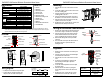
Overview:
Tamper switch
Vertical
adjustment screw
(without cover)
Cover
Cover
screw
Wire cable connector
Mounting plate
Hood
Beam
sensor LED
Terminal
block
Cable breakout
Captive screw
Beam sensor
Cable breakout
Note:
Depending on the monitoring system
used by the gate motor, it may be necessary to use either the N.C. output or
connect the included 10kΩ resistor to the N.O. or N.C. output. Please refer to the gate operator manual or the gate
operator manufacturer for the preferred monitoring method.
12
-
30V DC/AC
60Hz, 100mA
(Non-Polarity)
•
Polarity
does not matter for the power input.
• Connect the N.C. tamper terminal to the
tamper circuit of an alarm control panel.
Wiring Diagram:
N.C.
N.O.
COM
Tamper
N.C.
Relay
ENFORCER 33ft Polarized Reflective Photoelectric Beam Sensor
SECO-LARM U.S.A., Inc. 3
Mounting:
Alignment:
Solid green
Good beam signal,
properly aligned
Alternating flash
Poor beam signal
Solid red
No beam signal,
triggered
Wiring for the
Bottom Cable Breakout
1.
Unscrew the
four
cover screws and remove the
cover.
2. Loosen the captive screw and remove the sensor
from the mounting plate.
3. Using the included mounting screws, mount the
mounting plate to the wall.
4. Use the cable breakout and cable connector at
the bottom or rear of the sensor to run the wires.
5. Hang the sensor back on the plate and use the
captive screw to secure it in place.
6. Re-attach the cover, replace the four screws, and
attach the hood to the top of the sensor.
1.
Puncture the cable breakout
located at the bottom
of the sensor using a screwdriver or other object.
2. Insert the short end side of the cable connector
into the cable breakout hole and use the nut to
secure it, tightening with a wrench as needed.
3. Run the wires through the end cap and cable
connector.
4. Then screw the end cap into the external side of
the cable connector to prevent water from
entering the unit.
1.
Mount the sensor
and reflector so that they face
each other.
2. Connect power to the sensor. The LED will light
as indicated in the chart below.
3. Unscrew the four cover screws and remove the
cover.
4. To find the correct alignment, slowly turn the
lens assembly left and right to adjust the
horizontal angle.
5. Loosen the vertical adjustment screw to adjust
the vertical angle.
6. Place the hood on the sensor by sliding the
hood’s ridges into the slots on the sides of the
sensor.
7. Re-attach the cover, replace the four screws,
and attach the hood to the top of the sensor.
Lens
alignment
±90°
±5
°
Horizontal
adjustment
Vertical
adjustment
Cable
Connector
End cap
Sensor
Nut
Rubber
neck