SebArt New professional line Sukhoi 29S 50E ARF ASSEMBLY MANUAL The new Sukhoi 29S 50E ARF was designed by Italy aerobatic pilot, Sebastiano Silvestri and the design is based on of his new Tournament Of Champion’s competition airplane. This professional ARTF kit is the result of Sebastiano’s long research in 3D performance.
Table of contents Table of contents...............................................................................................................……….. 2 Required radio, motor and battery.............................................................................................…. 3 Additional required items, tools and adhesives.............................................................................. 3 Warning............................................................................................
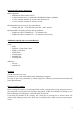
Required radio, motor and battery Radio equipment: • Minimum 4-channel radio system • 4 digital standard servo, recommended JR PROPO DS9401 or DS8301 • 2 servo extension 600mm, for elevator and rudder servos • 2 servo extension 100mm, for aileron’s servos Recommended electric motor for best performance: • Hacker A50-16S + X70 SBec-Pro controller + APC 16x10E Recommended Li-Po battery pack for best performance: • Flight Power EVO 3300mAh 6S.….for unlimited 3D • Flight Power EVO 3700mAh 6S…..
Using the manual This manual is divided into sections to help make assembly easier to understand and to provide breaks between each major section. In addition, check boxes ( ) have been placed next to each step to keep track of each step completed. Steps with two boxes indicate that the step will require repeating, such as for a right or left wing panel, two servos, etc. Rember to take your time and follow the directions.
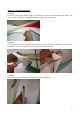
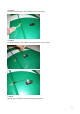
Section 1 – wing fillet installation step 1 Locate the carbon tube and the wing to the fuselage. Locate the corresponding wing fillet to the wing. Test fit the fillet and his alignment with the wing panel and fuselage. step 2 Once satisfied with the fit, glue the wing fillet to the wing panel using medium CA. Use the glue carefully avoid over runs onto the area to be covered with the material. step 3 Remember to check carefully the wing fillet/wing panel alignment.
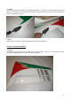
step 4 Use the covering iron carefully, at a medium temperature, to glue the cover material down around the area of the fillet. Use caution while working around areas where the cover material overlaps to prevent separating the covers. step 5 Repeat steps 1 through 4 for the remaining wing panel and wing fillet.
step 2 Carefully glue, with some drops of thin CA, each of the four hinges in the aileron. step 3 Locate the aileron and carefully glue, with some drops of thin CA, each of the four hinges into the wing panel. step 4 Work the aileron up and down some times to work the hinges and check for proper movement. step 5 Repeat steps 1 through 4 for the remaining wing panel. Section 3 – aileron servo & control horn installation step 1 Locate the following items included in the hardware pack and the servo.
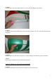
step 2 Install the servo hardware (gommets and eyelets) and put the servo into the wing panel, as per pictures. step 3 Drill using a 1,5mm drill bit, and install the servo into the wing panel using a Phillips screwdriver.
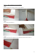
step 4 Glue the fibreglass horn with medium CA into the aileron. step 5 Install the hardware and make the final adjustment as per pictures. step 6 Repeat steps 1 through 5 for the remaining wing panel.
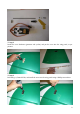
Section 4 – rudder installation & tail wheel installation step 1 Test fit the rudder into the fuselage, check for a correct alignment. step 2 Glue it carefully with medium CA. step 3 Insert the three hinges in their appropriate slots and glue them with some drops of thin CA.
step 4 Drill in the rudder, 20mm from the bottom, the location for the tail wheel using a 2mm drill bit. With the hobby knife cut a groove of 20mm length into the rudder. step 5 Than locate the items included in the hardware pack and assemble them as per picture. step 6 Drill on fuselage the screw locations for the tail wheel using a 1,5mm drill bit, and install it as per picture.
step 7 Carefully put some drops of medium CA into the 2 mm hole, carefully locate the rudder and glue the hinges with some drops of thin CA. step 8 Work the rudder right and left some times to work the hinges and check for proper movement. Section 5 – elevator installation step 1 Insert in the elevator the four hinges into their appropriate slots and verify the correct position and alignment of the elevator with the stabilizer.
step 2 Insert carefully the elevator through the fuselage. step 3 Insert the stabiliser into fuselage space and locate the elevator hinges into the stabiliser. step 4 Glue carefully the hinges in the stabiliser with some drops of thin CA.
step 5 Locate the carbon tube in his position and carefully check the alignment of the stabilizer with the fuselage, as per pictures. step 6 Once satisfied with the alignment, glue carefully with thin CA the stabilizer at the fuselage. Section 6 – elevator servo & control horn installation step 1 Locate the following items included in the hardware pack, servo extension 600mm long and servo.
step 2 Than install the servo hardware (gommets and eyelets) and locate the servo into the fuselage. step 3 Drill using a 1,5mm drill bit, and install the servo into the fuselage using a Phillips screwdriver. step 4 Glue the fibreglass horn with medium CA into the elevator. Than install the hardware and make the final adjustment as per picture.
Section 7 – rudder servo & control horn installation step 1 Locate the following items included in the hardware pack, servo extension 600mm long and servo. step 2 Than install the servo hardware (gommets and eyelets) and locate the servo into the fuselage. step 3 Drill using a 1,5mm drill bit, and install the servo into the fuselage using a Phillips screwdriver.
step 4 Glue the fibreglass horn with medium CA into the rudder. Than install the hardware and make the final adjustment as per picture. Section 8 – landing gear & wheels installation step 1 Locate the following items included in the hardware pack.
step 2 Locate the landing gear on the fuselage and fix it with the screws included in the hardware pack. step 3 Sand with the sanding paper the inside of the wheel pant; locate the wood reinforcement, glue it with some drops of medium CA and drill the location for the wheel axis screw using a 3mm drill bit as per pictures. step 4 Install wheel and wheel pant as per pictures.
step 5 Drill the location for the wheel pant fixing screw using a 1,5mm drill bit and than fix the wheel pant with the screw included in the hardware pack. step 6 Test fit the L.G. Lift Generator and his alignment with the fuselage. step 7 Glue carefully the landing gear fillet with some drops of medium CA, as per picture. step 8 Repeat steps 3 to 7 for the other side of the landing gear.
Section 9 – electric motor installation For best performance, we recommend to use HACKER motor. step 1 Locate the engine mount on the fuselage, fix it using the four screws included in the hardware pack and than glue it carefully with medium CA. step 2 Locate the motor and fix it with the four screws included in the motor hardware pack.
step 3 Locate and fix the ESC and his switch as per picture. step 4 Glue with some drops of medium CA on side of the Velcro strip included in the hardware pack. step 5 With the hobby knife open the cooling holes in the fuselage as per picture.
Section 10 – glow engine installation (option) If you want to install a glow engine, you need the hardware pack and the reinforcement wood parts set, that is available as optional. Visit the website WWW.SEBART.IT for price and for download the manual instructions for this special application. Section 11 – cowl installation step 1 Apply a piece of masking tape on the line were you have to make the holes for the cowl fixing screws, than mark the position as per the picture.
step 2 Slide the cowling onto the fuselage and install the spinner back plate. Then apply another piece of masking tape on the same line of the one applied before. Drill the location for the four self-tapping screws using a 1.5mm drill bit. step 3 Attach the cowl using the four self-tapping screws, included in hardware pack, and a Phillips screwdriver. step 4 Fix carefully the prop and the spinner.
Section 12 – final radio installation Install the receiver, two extension 100mm for aileron servos and the battery pack as per the picture. Wings installation Locate the wing panels and fix them using the two nylon screws, included in the hardware pack, and a Phillips screwdriver.
Decal set application Control throws Please, follow carefully the recommended linkage setups for ailerons and elevators.
Rates and expos Use the recommended expos to soften the feel of the model, expecially on high 3D rates. The goal is to get the model to feel the same around neutral as it does on low rates. Use low rate settings for all flying, included starts and landings, and high rate for 3D aerobatics. For precision flying or general sport fliers, the low rate throws are perfect, even for snap rolls. When doing 3D aerobatics, flip to 3D rates just before the manouer.