ManualNo:26110701 Developmental Resources E L I T E M O D E LN U M B E R S : 110.42822200110.42832200 110.42824200110.42826200 110.42834200 110.42836200 110.42922200110.42932200 110.42924200110.42934200 110.42926200110.42936200 HEt'" HE{" Front-Loadi ng Automat i c Washer FIELD COURSE9373 Developmental Resources @ 2001 Sears,Roebuckand Co.
TABLE OF CONTENTS SAFETYFTRST MODEUSERIAN L U M B E RP L A T E. . . . . . . . . . . . . . TNSTALLATTON CONSTDERATTONS I n s t a l l a t i oR n e q u i re me n ts........... Installation Instructions(Washer)................ Installation Instructions(Pedestal).............. TH EO R Y O FOP E R A T T ON S c o M P o N EN TA C C E S S ............... C o m p o n e nLt o ca ti o n ComponentAccess c o M P o N EN TT E S T |N G.............. CentralGontrolUnit.......... ComponentChecks M o t o rC o ntro U l n i t..
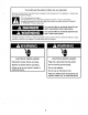
Your safety and the safety of others are very important. We haveprovided manyimportant safetymessages in thismanualandon theappliance. Alwaysread andobeyallsafetymessages. This is the safetyalertsymbol. This symbolalertsyou to potentialhazardsthatcan killor hurtyou and others. All safetymessageswill followthe safetyalertsymboland eitherthe word 'DANGER" or "WARNlNG." Thesewordsmean: You can be killed or seriously injured if you don't immediatelyfollow instructions.
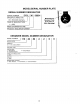
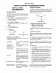
PLATE MODEUSERIAL NUMBER SERIALNUMBERDESIGNATOR SER|A NLU M B E R I c s l L MANUFACTURING-ITE I CS= Shorndorf, Germany I ffi L = 2001 W EE KO F M A N U F A C T U R E Model/Serial Number Plate (Left side of Door Opening) P R O D U C TS E Q U E N C EN U M B E R KENMORE MODELNUMBERDESIGNATOR M o p E L N U M B E R1 1 0 4 2 g2 | | | PRODUCT 42 = Front-Loading Washer COLORCODE 2 = WhileMhite 6 = Graphile/Graphite Y E A RO F I N T R O D U C T I O N 2 = 2001 DECADE 0 = 2000 E N G I N E E R I NCGH A N G E 0 = B
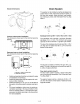
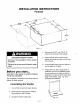
SectionOne I NSTALLATION CONSIDERATIONS OptionalPedestal INSTALLATION REQUIREMENTS A pedestalmay be purchasedseparatelyfor this w a s h e rT. h i sp e d e s t a l w i l l a dadb o u t1 4 i n c h e st o t h e heightof yourunitfor a totalverticalheightof approximately52 inches(132cm). Toolsand Parts Assemblethe necessarytoolsand suppliesbeforebeginningthewasherinstallation. The partssupplied are in the washerdrum. Tools neededfor connecting the water inlet hoses . Pliers(thatopento 1 9/16in. [39.5mm]) .
DrainSystem WasherDimensions | : ,','r I l l l i i i "',', , ,, ,li{',, 11. . r' ir. '., i -'i canbeinstalled usingthestandpipe drain Thewasher (floor wall), the laundry tub drain system, or or system hose installaSelectthedrain thefloordrainsystem. PartsYouMay tionmethodyouneed.(See"Alternate Need.") : :;*::, i;sl tt+,,i.,,.
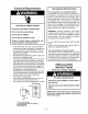
ElectricalRequirements INSTRUCTIO N S GROUNDING For a grounded,cord-connectedwasher: Thiswashermustbe grounded.In the eventof a groundingwill reduce malfunction or breakdown, the riskof electricalshockby providinga path of for electriccurrent.This washer leastresistance is equippedwith a cord havingan equipmentgroundingconductorand a groundingplug.The plug must be pluggedintoan appropriate outlet grounded properly installed is and in accorthat dancewithall localcodesand ordinances.
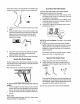
Connectthe InletHoses Thereare 4 boltsin the rearpanelof the washerthal supportthe suspension svstemdurinqtransportation. Connectthe inlet hosesto the waterfaucets Makesurethewasherdrumis empty. to the 1. Attachthehosewiththeredcolorindicator Screwon coupling by handuntil hotwaterfaucet. it is seatedon thewasher. to the 2 . Attachthehosewiththebluecolorindicator Screwoncoupling by handuncoldwaterfaucet. til it is seatedon thewasher. withan additighten thecouplings 3 . Usingpliers, turn.
Levelthe Washer Properlylevelingyour washer preventsexcessive noiseand vibration. 1. Checkthe levelness of the washerby placinga levelon the top edgeof lhe washer,firstside-toside,thenf ront-to-back. 3. 4. 5. 6. 7. L i- Checkto besureyouhaveallof yourtools. materials. allpackaging Dispose/recycle areon. Checkto besurethewaterfaucets faucets andinlethoses. Checkforleaksaround 3 prongoutlet. Plugintoa grounded Use.
I NSTALLATIONI NSTRUGTIONS Pedestal t.5ct' l5^7tf,l1 til.gr*f' l{t.t !tlr rT i :h. i ..1;.; 1". i 1l' {5 f ctrri -l 'o\*l*--Fig. 1-l "HOT"and"COLD"fill hosesfromthe backof the washer. 4 . Remove the EXCESSIVEWEIGHTHAZARD Use two or more people to move washer and dryer. thedrainhosefromthe 5 . Disconnect Failureto do so can result in back or other injury. 6 . Pullthewasherawayfromthewallso it washeranddrainanywaterin the hose intoa bucket. canbe tippedon its back. 7 .
Installingthe Pedestal 1t . z. Openthe pedestaldrawer.Remove theenvelope tapedinsidethedrawer. Thisenvelope contains four(4) # 1 2 x 5 /8 "(1 .6cm)h e xh e a dsheet metalscrewsthatwillbe usedin Steps 4 a nd5 . Remove the Phillips headscrewfrom bothdrawersidesandsettheaside. (Fig.1-3) Removethe drawerandset it aside.Pushtheslidesbackintothe pedestal. Liftthe pedestaltowardthe frontof the washerand installthetwo (2) remaininghex head sheet metalscrews. Do not tiqhten completely. 6.
Fig. 1-6 10.Whenthewasheris level,usea wrenchto 9/16"(14.3mm)open-end securely tightenallfour(4)feetlocknuts againstthe pedestal.(Fig.1-7)The locknutsmust be tightened. loc*nul----l Fig. t-7 11.Pullbothdrawerslidesoutandreassemblethedrawerto thedrawerslides withthetwo(2)Phillips headscrews. (Fig.1-8)Useof the two (2)dividersis optional. Closethedrawer. Fig.
SEGTION 2 THEORY OF OPERATION INTRODUCTION present TheHFand HEt Front-Loading Automatic Washers a number of newfeatures andoperating quite previous characteristics differentfrom models.In additionto the introduction of front-loading operation,the HF andHEt containa numberof uniqueoperatingfeaturesdesignedto increase clothes cleaning abilitywhileoffering veryhighwaterandenergyconservation.
for compartments Thedispenser drawerhasfourseparate products to thewashload.Thesecompartaddinglaundry mentsare: 1. 2. 3. 4. Compartment PrewashDetergent MainWashDetergent Compartment BleachCompartment FabricSoftener Compartment are dilutedand dispensed automatically Laundryproducts at the propertimeduringthewashcycle. Fig.2-3 andMainWashDeterTheseparator betweenthe Prewash gentCompartments canbe movedto accommodate either (Fig.2-a) liquidor powdered detergents.
Pressure Switch PressureSwitch The pressureswitchis locatedin the top rightrearcornerof the washer (Fig 2-7) This switchsenseswater levelin the wash tub. The controlsignalfrom the pressureswitchis sentto the CentralControlUnitand is usedto determinethe amountof waterintroducedintothewashtub durinothewash cycle. The pressureswitchalsosensesthe sudslevelin the wash tub. lf excessivesudsingoccurs,the washerstartsan automaticsudsroutine.The displaywillshowthewordSUDS.
OptionSelection - = Not Available D = Default,X = Available, .1 c I U J o U o z U g z cl D z - d I c d l g E o ,1d = < l f z ) a I U ,u I (, =u ;6 L J -' E o x a f iE J 6 .lJ ',.ti U I F ' ^ c D n o q U a .,i o t F 2 6 - o ..E ( r! E n n ! I -E n a L n $F Ie l J 6 r O ) x x l 3 e ( l, ( t x .
Modifiers M00ltl!n! a .-"1.i nt4ti, 11{tAl '..i-Artl{l sildk . r') filr',sf Iti') t l H r l f/ f ( , 1 a I r ' f ^ ! r lrti^ fcAlt'l J r'r^F[' ' Mrlrr']t''j a l4iAti4lf${.ti a Lilr. a r a fst D / {:,)ttl tirfi* l{1r" a Iiltl }p,f'l lAp f{}rfi I trf]1.0 , 1 L,-"] \*-i woii:iE *o ' a ir'' ir a f t { } t i r : 1l f , t ,',:'.'t ltrftr Sfr1, I ll'{'fr ' L{:}ur ' o{1' r*'' ['iln$rcrrl! 5i(N'(r Fig.
. Tochangethewatertemperature, selectthe 2. Selecta WashCycle. TEMPbuttonuntilthedesired WATER 3. SelectAUTOSOAK. settingglows. NOTE:Forcycleswithhotwashtemperatures, . Tochangethespinspeed,selecttheSPIN thesoaktemperature willbe setto warm; SPEEDbuttonuntilthedesiredsetting willbe the otherwise, thesoaktemperature glows. sameas thewashtemperature. . Tochangetheloudness of theEndof Cycle 1 4. SelectandholdSTART(approximately selectENDof CYCLESIGNAL . Signal, thewasherdrains second).
CentralControlUnit(CCU) The CentralControlUnitis locatedat the top rearof the washerandis enclosed ina controlbox.(Fig.2-11) Thereare parts noserviceable insidethecontrolbox.lf diagnostic tests indicate anycomponent of the CCUis defective, theentire controlboxmustbe replaced. TheCCUreceives inputlromthetouchpad/LED assembly anddirectly controls thedispenser, drainpump,waterinlet valves,doorlockingand unlocking solenoids, and heating element relay.
Drain Pump PumpMotor A separatepump/pumpmotoris usedto drainthe wash lub. (Fig.2-14) The pump motor is 120 VAC and is attacheddirectlyto the pump. The pumphas a clean-out filterlocatedat the frontthat allowsfor the removalof large objectsthat may have passedfrom the drum. (Fig.2-15) Fig.2-14 Fig.2-15 EcoValve valvethatcloses Thewasherhasa specially designed duringthewashportionof thecycleso that100%of the wateranddetergent mixtureis usedon thewashload.
HeatingElementandTemperature Sensor HeatingElementRelay ModelHF provides a heating element to increase thewatertemperature duringcertain washcycles.Thetemperature sensoris used withtheheaterto monitor watertemperature in thetub.(Fig.2-18) A relayis usedto turntheheating element on heating element relayis located in andoff. The thelowerright-hand sideof thewashercabinet. (Fig.2-21)TheCCUoperates a solenoid to providing relay contacts, 120 closethemain VACto theheating element.
SectionThree GOMPONENTACCESS COMPONENT LOCATION DETERGENT DISPENSER VENTHOSECONSOLE F TUB ASSEMBLYi WASHERBACK PULLEY WASHERFRONT DRIVE MOTOR MOrOR/l CONTROLUNIT{ DRAINPUMP ASSEMBLY 3-1 HEATING ELEMENT IELAY
ACCESS COMPONENT RequiredTools T h eSo u r c e11 0 FrontLoadingWasherrequiresthe use of MetricSocketWrenchesof various and a s i z e sT, o r xT - 1 5 T-20 , and T-25 Drivers,a CrescentWrench,a flat bladedscrewdriver ha m m e r . ACCESSING INTHECONSOLE COMPONENTS Assembly. Components accessible intheConsole include CoverandtheTouchPad/LED theConsole Accessto thesecomponents requires thatthetopof thewasherbe removed. Removingthe WasherTop Threescrewssecurethewashertopat the back of the washer.
Thereare ninetabssecuringtheTouchPad/LED Assemblyto the console.(Fig.3-9)A flat bladed screwdriver willbe helpfulin releasing thesetabs. Typical Release Tab Releasethesetabsin sequencefromleftto right aroundthe TouchPad/LEDAssemblyuntilallof the tabsare freeand the Assemblycan be lifted fromthe console.(Fig.3-9) Tab Tabl Fig.3-9 Fig.
R E M O V I NTGH EB O O T F R O MT H ET U BA S S E M B L Y REMOVING THEWASHER FRONTPANEL Removingthe washerfrontpanelwillrequirethat the doorswitchbe removedand the bootbe separatedcompletelyfrom the front panel opening. Theconsolemustalsobe removed. Next,removethe threescrewssecuringthe toe panel to the front of the washer (Fig.3-1a) and removethe tow panelby liftingslightlyand pulling forward. , ,**ru-**--,**,_ fromthe removed The bootcan be completely assembly.
R E M O V I NTGH ED E T E R G E N T D I S P E N S EARS S E M B L Y hosef romthedetergent Disconnect theoverflow (Fig.3-17) assembly. dispenser the detergent disThe Detergent Dispenser Assemblyis located Removethe screwsecuring penser the top left frame member. assembly to underthe washertop. Beginby removing the (Fig.3-17)Slidethe assemblybackslightlyand washertop,consoleand frontpanel. out. lifttheassembly Separate thewaterinletandwindow washer tube Vent fromtheboot.
THEDRIVEMOTOR REMOVING REMOVING THE MAINCONTROL BOX ANDPRESSURE SWITCH oncethe back Thedrivemotorcanbe removed panelhasbeenremoved. The maincontrolbox is a singleassembly and parts.lt canbe Twelvescr ewssecur ethe backpanelt o the doesnotcontain anyserviceable the 12screwsandremovethe removed it washer.Remove by liftingthetopplastictabssecuring theDriveBelt. to the backcabinetframeandslidingit towards backpanel. Remove thefrontof the washer.(Fig.
Toremove thepumpassembly, beginbyopening A C C E S S I NTGH E the doorcovering the wiringharnessconnector MOTOR CONTROL UNIT fromthepump anddisconnect thewiringharness Unit mayrequire motorterminals. Remove thescrewsecuring the Accessto theMotorControl the leftfrontshockabsorber. pumpassembly to thewasherframe.(Fig.3-24) removing liftupon the Oncethe pumpis removed the drainhoseand Usinga flatbladedscrewdriver, plastic front right tab under the corner of the tubeoutlethosecanbe removed. (Fig.
REMOVING THEHEATING ELEMENT ANDTEMPERATURE SENSOR Each weightis securedto the tub by three 13millimeterbolts. (Fig. 3-31)Remove the three boltsand liftthe weightfromthe tub. Disconnect from the wiringharnessconnectors the heating terminals element andloosenbutdo n o t r e m o v et h e 1 0 -mi l l i me te n ur t b e tween the (Fig. heating terminals. 3-29)Then slide element the heatingelement fromthetub.Slidethetemperature sensorfromtheheatingelement bracket.
The tub is heldin positionby fourshockabsorbers, two in f ront (Fig.3-33) and two at the back. (Fig.3-34)Eachshockabsorbercan be disconnectedf romthe tub by turningthetop of the shock mountcounterclockwise,90o. The shockcan be removedfrom the washerby turningthe bottom shockmountcounterclockwise, 90'. Removethe screwsecuring the leftend of the pressure tubeconnector to thetub. Then,press downon theplastictabsecuring therightendof thepressure tubeconnector andpullit fromthe tub.(Fig.
The two piecetub is heldtogetherwitha number of metalclampswhichcan be removedby prying them off with a flat bladedscrewdriver.(Fig. 3- AG ND REASSEMBLIN R E I N S T A L L I NTG HE T U BA S S E M B L Y s7) the tub When reassembling and reinstalling assembly,take note of thesespecialprocedures. 1. When reassembling the tub, be sure to installall the metalclipsall around the tub.A hammermay be necessary to do this. 2.
SectionFour C O M P O N E N TT E S T I N G CENTRAL CONTROL UNIT ConnectorLocation 1. 2. 3. 4. 5. Pressure Switch Temperature Sensor Dispenser Switch/Motor lnlet Valves DrainPump 6. Door Lock Solenoids 7. Motor Gontrol Unit Power 8. Door Lock Main Switches 9. Heating Element Relay 1 O .L i n e F i l t e r {l.Serial Gomm Link l2.Touchpad/LED Ribbon Gable l3.Door Switch 14.
)g ELECTRICAL SHOCKHAZARD Disconnectpowerbeforeservicing. Replaceall panelsbeforeoperating. Failureto do so can resultin deathor electricalshock. CHECKS COMPONENT on the Continuity checkscanbe madeon variouscomponents of thewasherfromtheconnectors thewasherfromthewall CentralControlUnit. Beforeperforming anyof thesetests,disconnect fromtheCentralControlUnitbefore outlet.In addition, disconnect thewiringharness connector makinganycontinuity tests.
Waterlnlet Solenoids Hot Water Solenoid Cold Water Solenoid TestPoints Reading 7to5 3to1 800 ohms 800 ohms DrainPumpMotor oll4'& !!*.; em ::: , "- TestPoints Reading 2lo 1 1 5o h m s *lH ' I Door Locl
HeatingElementRelaySolenoid Iq: b# Y{, Test Points Reading 2lo 1 1 5o h m s DoorSwitch \ Door Closed Door Open Test Points Reading 2lo 1 2lo 1 0 ohms Infinity MOTORCONTR OL UNIT Connector Location : a I -''*J I - --'q Power Supply Motor Connector Serial Gomm Link _i ) *ii".1;1.
LINEFILTER TestPoints AtoB=0ohms CtoD=0ohms DISPENSER ConnectorLocation Dispenser Motor Dispenser Switch Dispenser MotorContinuity Check- 1400Cl 4-5
PRESSURE SWITCH ConnectorLocation 2 2 2 4 2 1 2 6 1 11 4 B l a n k WaterLevel ContactsMade Empty SudsDetect Level1 Overflow 21 lo 22 1 1t o 1 4 21 to 24 21 lo 26 SENSOR HEATING ELEMENT ANdTEMPERATURE ConnectorLocation HeatingElement Heating Element Terminals TestPoints Reading BetweenTerminals 15 ohms Temperature Sensor 32'F (o'C 122"F (50" Temperature Sensor Terminals 2 0 3 ' F ( 9 5 "C ) RELAY HEATING ELEMENT SOLENOID 4-6 = 15ohms
SectionFive D I A G N O S I SA N D T R O U B L E S H O O T I N G SUDSDETECTION DuringDrainRoutine DuringtheDrainRoutine, Normaldrainwilloccuruntilthe thewaterlevelis checked continuously. pressure switchsensesno waterin thewashtubandthereis no foam(suds).Thedrainpumpwill operatean additional 15 secondsafterthe pressureswitchreportsno wateror foam. lf thedrainroutineoperates switchsensesanyfoam(suds)in forfour(4)minutes andthepressure "Kill-Foam" (Seedescription of this Routine.
DOORLOCKING ANDUNLOCKING Locking TheDoorLockingRoutine willonlystartif thedooris securely closedandthe DoorSwitchContact is C L O SE D . 1. TheDoorLockRelayis energized whenever a washcycleis started.Therelayis operated for40 milliseconds. by thecentral 2. Duringthe nextthree(3)seconds, thecontacts on thedoorlockarechecked controlunit areCLOSED. thisroutineis finished. a. lf thecontacts the theCentralControlUnitenergizes b.
DetectionRoutine Unbalance Therearethree(3)Unbalance checkspriorto thewashergoingintohighspeedspin. Check1 Thischeckoccursduringthedistribution ramp(whilebasketspinis accelerating f rom40 to 100 rpm). a. lf the MotorControlUnitdoesnotsensean unbalanced condition, therampwillcontinue. b. lf theMotorControlUnitsensesan unbalanced condition, thedrivemotoris stopped.lf the repetition counter for lowspeedspinis equalto 0, theCentralControlUnitwilladvance to thenextspinroutine.
ERRORCODES No waterdetectedenteringmachineor Pressureswilch trip not detected. machine lf after30 seconds thecontrol andthen doesnotdetectwaterentering off will displayed. valveswillbeturned andtheerrorcode be Or lf thecontrolhasturnedthewatervalveson andafterB minutestheflowmeterhas 10.5gallons of waterpassing through it,buthasnotdetected thepressure detected switchtrip,thevalveswillbeturnedoffandtheerrorcodewillflash. PressPAUSE/CANCEL twiceto clearthe display. PotentialCauses . . . . . . . .
ERRORCODES Drive Motor Tachometer Error The controlis unableto properlydetectmotorspeedand the machinewillshutdown. lf a failureoccursduringhigh-speed spinthe doorwillbe unlockedafter3 minutes. PotentialCauses . . . . Checkwireharnessconnections betweenthe DriveMotorand the MotorControl Unit(MCU),and betweenthe MCU and the CentralControl Unit(CCU) Replacethe DriveMotor Replacethe MCU Reolacethe WireHarness MotorControlUnit Error TheCentralControlUnithasdetected a shortin themolorcontrol unit.
ERRORCODES SerialCommunicationError Communication betweenthe CentralControlUnit(CCU)and the MotorControlUnit (MCU)cannotbe sentcorrectly. PotentialCauses . . . . . . to the MCU.the motor,and CentralControl CheckWire Harnessconnections U n i t( C C U ) Checkthe Drivesystemlor any wornor failedcomponents ReplaceMCU ReplaceCCU ReplaceMotor ReplaceWire Harness Dispenser CircuitError lf thedispenser motoris notableto bedrivento it'sproperposition. PotentialCauses . . . motorto thetopof thedispenser.
ERRORCODES PotentialCauses . . . . . . . lf too muchdetergentwas used,runthe unitthrougha Rinse/Spincyclethena Normalcyclewithoutaddingany detergent. Thisshouldclearthe unitof the excessdetergent. Checkthe drainhoseand makesureit is not pluggedor kinked CheckWire Harnessconnections to the DrainPump,PressureSwitch.
DIAGNOSTIC TEST Thecontrolmustbe in theOFFstatebeforepressing to startthetest. thetouch-pad sequence Startingthe test mode Closethe door. Selectthe DRAIN/SPIN cycle. SelectNO SPINby pressingthe SPINSELECTbuttonfive (5) times. Push PrewashOptionbuttonfour (4)timeswithinfive (5) seconds.C:00will show in the display. lf the Startingprocedurefails,push PAUSE/CANCEL button.Then repeatthe startingsequence. TestProgramControlduringExecution pushPrewashOptionbuttontwo (2)times.
MotorContinuityTest Disconnect fromthemotorandmeasure of themotorwindings. thewireharness theresistance P i n 1 t o P i n2 Normal= approximately 6Q Abnormal= infinitv P i n2 to P i n3 Normal= approximately 6Q Abnormal= infinity Pin 1 to Pin 3 Normal= ?pproximately6 Q Abnormal= infinity WaterTemperature Sensor Disconnect fromthewatertemperature sensorandmeasure the resistance of the thewireharness sensor.
TROUBLESHOOTING GUIDE WON'TPOWERUP. (Touch-pads do notrespond whenpressed) WON'TSTARTCYCLE Checkthe linevoltageand for blownfuses. Checkfor voltagegoingto CentralControlUnit(CCU)by listen i n gf o r a c l i c k i n t h e C C Uw h e nu n i ti s p l u g g e di n . l f n o c l i c k replaceCCU. Unplug the unitbeforecontinuing. Checkcontinuity of linecordand linefilter. to CCU. Checkharnessconnections Checktouch-pad/LED assembly. 1. Openandclosethedoor.Thedoorhasto be openedbetween washcycles.
O V E RF I L L S DRUMWON'TROTATE 1. 2. 3. 4. 5. 6. Verifythe unitis level. Checkpumpdrainsystem- thiscouldindicatea lailureto drain. CheckOperatingPressureSwitch. CheckPressureSwitchhose. CheckFlowMeterooeration. Checkthe CCU. 1 CheckDrivebelt. CheckDrivemotor. CheckWireHarnessconnections. CheckMotorControlUnit. z e 4 MOTOROVERHEATS 1 2 e 4 connections. CheckWireHarness CheckDrainpump. CheckDrainpumpmotor. 4 , CheckthattheDrainhoseandDrainPumpFilteris clearof foreignobjects. ChecktheCCU.
THECYCLECHARTS READING SampleCycleChart handwash Movement . . . perminuteof basketspin. Speed(rpm)- Revolutions for 1.5seconds, stopfor Reversing In thisexample thebasketwillrotatecounterclockwise andthenrepeat for 1.5seconds, stopfor 30.5seconds 30.5seconds, thenrotateclockwise of thecycle. thesequence throughout thewashandrinseportions in thechartson pages5-20througn5-22. In this SpinCycle Thespincycleis described cyclewillusethe LS3spinprofile. example theHandWashable Level .
Pump . Ll +15s- Thepumpwillturnon anddrainthetubto lowestfilllevel,(SudsDetect), andthenrun for an additional 15seconds. Options . 2nd rinse - lf thisoptionis selectedby the consumer,this line indicateswhen it will occur duringthe maincycleand it's duration.
E ; E G U) t a a t o e { ol a) @ ol q @ a E E i ; ; 8 I ! o I a E C o o c sl sf t t (r) @ ( - E ol q o E a a o o ol (o ! ( E g v l N @ 6l a o E :g I t,, d o (\l E F - N O F 3 E 3e
o c n fi o c c, c @ o o ol (o a p (r) @ 6l \l E ! ! !1 ; 5 ci E a ! o o E c ol rf c) @ ol c 3 a o E a a d o ( E( s c? ol (o ol € c = ' 6l a o c g 1 ' 3* d o I 9 o 6l .
0) t o G c c c E t c c (f. O o o o E c? O 6l = c) € s a @ I c F @ 6l o o o q d o ol \t c o a o o fi ! c (n (r) @ E c'l c q a 6 o o ot a o E C q o = E d o ol ; -Qu - o o o @ ot @ i E 3e ol @ q o = 6 c o E E o o o o ' 3 .
o o (\l (o o Eo a J x o (v) @ 13 o c.) O 6 :/ ot a o o rt) o o o o o (\l o I E E c.) ! o I t \ o i \f d a) i \ @ ol a o o o 'i o o (\l (o .g c .9 z N @ ; c q E c o o !t (\ N c a! a o E n u C9 '\ 3 E o o ol r+ rO, o o 'tr ol 6 ol so o 6o q o o fft E 3 c &"^::t: il; F E d o ol ol a) @ ol $ ci lll - O x z 6 .! G x o .= Ici uJ= * o tl E o o !t o o o G o (0 E - o e,; = 6 Z E o 6 c) a c a 3 E 'r- @ E q ,; E i .
t E @ 7 c ') ( : c c T E I 1' ) c 0 I n o o N (o c) o) a r) N D c c G o o o |r) o o ol a o h E e o
E E (o ) c E o ! t n c I f c N c o f, o o ol (o a) o) ol R o o 5 c !, t! E i ,: J I n c al, c t I o n c c o E I o a ) I o o ,c @ 6l ( i g D J O c o n E N a c c o) 6 R = !, (\l o o s (o o s - E ! c t $ (9 o) o N a c a o a o o ; o o J qf t ot o) E o .9 I 3 E $ c G ! c 6 o o o o o (o a E o ( E oa ( (., I 6l a o I l u ? o o o c I G ' I 'fi E c) o) 6l q I o 3 E O o c 3 a ::r.i::;ila :1i:;:ti1!;1.
K E N M O RM E I DR A N G E ModeIs : 110.42922200, 110.42I 32200,110.42924200,110.42934200, 110.42926200. 110.42936200 handwash - o i o ;- >o E rash phase ;peed lrpml n )n:X sec/ off=ySec 0 mainwash 31 'eversrng 1 . 5 / 3 0 , 51 5 / 3 0 . 5 n 0 0 0 rnse 31 .t (/?1 rinse soft a d d i t i o n a lr i n s € ( 0 0 n n 31 0 1 . 5 / 3 1 .
SpinCycleLS2 5-21
SpinCycleLS3 SpinCycleLS4 SpinCycleES 5-22
SectionSix WIRING DIAGRAM - i'. oz PLi p-L_l I iI cf{ v{-j r a z l M S 22 -l pe!l--j I ' r l . - . - . - . : FTLTER p-%gl-_i I
+T[",1 ffi"S MANUALDOORLATCH To Manually unlockthedoorlocksystem: 1. 2. 3. 4. 5. 6. Unplugthe powercordfromthe outlet. Removethe lowertoe panel. Reachup alongthe insideof the frontpaneland locatethe bottomof the doorlatchassembly. Locatedon the bottomof the door latchassemblyis a tear-dropshapedtab. Gentlypullthetab downabout/q" or unlila clickis heard. The door may now be opened.
Er-TMTNATE AcctDENTs Y,"u O,^ C"r^4"1cLt^,444, , o laW",illWl