http://www.managemyhome.com WASHING MACHINE SERVICE MANUAL CAUTION READ THIS MANUAL CAREFULLY TO DIAGNOSE PROBLEMS CORRECTLY BEFORE SERVICING THE UNIT. MODEL : 796.4219#90# , 796.
P/No.
CONTENTS 1. SPECIFICATIONS ............................................................................................................... 3 2. FEATURES & TECHNICAL EXPLANATION ....................................................................... 4 3. PARTS IDENTIFICATION ................................................................................................... 7 4. INSTALLATION AND TEST ................................................................................................ 8 5.
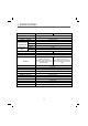
1. SPECIFICATIONS ITEM 4102#9## 4219#9## COLOR White, Patina Beige, Sears Red POWER SUPPLY AC 120 V, 60 Hz PRODUCT WEIGHT 204.8 lbs (92.
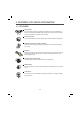
2. FEATURES & TECHNICAL EXPLANATION 2-1. FEATURES ᆺંቚ လ Ultra Capacity The Larger drum enables not just higher head drop and stronger centrifugal force, but also less tangling and wrinkling of the laundry. Heavier loads, such as king size comforters, blankets, and curtains, can be washed. Direct Drive System The advanced Brushless DC motor directly drives the drum without belt and pulley.
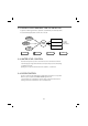
2-2. NEURO FUZZY WASHING TIME OPTIMIZATION To get the best washing performance, optimal time is determined by the water temperature, the selected washing temperature, and the size of the load. water temperature washing time selected washing temperature NEUROFUZZY the best washing performance rinsing time spin rhythm, time load size SENSING PROCESSING DETERMINATION EFFECT 2-3. WATER LEVEL CONTROL This model incorporates a pressure sensor which can sense the water level in the tub.
2-5. THE DOOR CAN NOT BE OPENED While program is operating. When a power failed and power plug is taken out in operation While Door Lock lights turn on. White the motor is in the process of intertial rotating, through the operation is paused. 2-6. CONTROL LOCK Use this option to prevent unwanted use of the washer. Press and hold CONTROL LOCK button for 5 seconds to lock/unlock control. When CONTROL LOCK is set, CONTROL LOCK lights and all buttons are disabled.
3.
4. INSTALLATION & TEST 1 Before servicing, ask the customer what the trouble is. 2 Check the setup (power supply is 120V, remove the transit bolts, level the washer...) 3 Check with the troubleshooting guide. 4 Plan your service method by referring to the disassembly instructions. 5 Service the unit. 6 After servicing, operate the appliance to see whether it functions correctly.
9
7 TEST OPERATION 1 Preparation for washing. 2 Press the POWER button. • Connect the power plug to the outlet. • Connect the inlet hose. 6 Check the water heating function. • Press the WASH/RINSE button • • • • Check the drain and spin functions. Press the START/PAUSE button. • Listen for a click to determine if the door has locked. 5 Check the automatic reverse rotation. • Check if the drum rotates 4 8 Press the START/PAUSE button. Check the water supply.
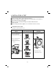
5. OPERATION 5-1. CONTROL PANEL FEATURES 796.4219#9## 796.
H I F A B A POWER (ON/OFF) BUTTON E D G C E SPECIAL CYCLE AND OPTION BUTTONS Press to turn the washer ON. Press again to turn the washer OFF. NOTE: Pressing the POWER button during a cycle will cancel that cycle and any load settings will be lost. The door will unlock after a brief pause unless the water level or temperature is too high. B CYCLE SELECTOR KNOB Turn this knob to select the desired cycle. Once the desired cycle has been selected, the standard presets will be shown in the display.
5-2.
5-2.
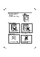
5-3. CYCLE OPTIONS ADD STEAM ADD STEAM cycles include the Steam Refresh, Normal/Casual, Bulky/Bedding, Kids Wear, Heavy Duty and Whitest Whites. Adding steam to these cycles provides superior cleaning performance while reducing energy and water consumption. By using a hot steam spray from above and cooler water below, fabrics get the cleaning benefits of a super hot wash, without the energy usage or potential damage to fabrics. The door may become quite warm during steam cycles. This is normal.
5-4. SPECIAL FUNCTION CLEAN WASHER A buildup of detergent residue can occur in the wash tub over time and can lead to a mildewy or musty smell. The CLEAN WASHER cycle is specially designed to remove this buildup using bleach or other cleaner designed specifically for cleaning front load washers. The CLEAN WASHER cycle should be run once a month, or more often under heavy use conditions or if odor is present. NOTE: Do NOT use this cycle with clothes, and do NOT add detergent or fabric softener.
5-5. EXPLANATION OF EACH PROCESS No. Process Explanation 1. Stay • Electrical power is supplied • Washer is ready to work and the micom is in the active mode. 2. Water supply • After loading laundry and selecting a course and a cycle, water is supplied and drum rotates. • When a user selects Pre-wash course, water is supplied through pre wash valve. 3. Soaking & washing laundry • To get laundry wet, drum rotates clockwise and counterclockwise.
No. Process Explanation A. Intermittent spin • To reach the correct set speed, the motor rotates clockwise and counterclockwise directions after spin process starts. • If the water level frequency is lower than 23.0 kHz, a washer senses suds and starts suds removal process. B. Rinse spin • In this process, the remaining water during washing process is extracted and the selected speed is kept. • Removing suds process is in active mode at this cycle. C.
19 Kids wear Express Wash Cold Clean Heavy Duty Whitest Whites Normal /Casual Bulky /Bedding Sanitize 120 120 50 44 25 40 19 22 34 20 16 11 61 120 120 NOTE: Cycles are different depending on the models 120 20 97 20 63 80 75 59 59 100 6.
20 Steam Refresh Handwash /wool Workout wear Rugged 120 120 20 23 26 59 11 53 120 120 NOTE: Cycles are different depending on the models 120 20 58 53 100
7. TEST MODE 7-1. SAFETY CAUTION There's built-in AC 110V and DC power in output terminal of PWB assembly in common. Be careful electric shock when disconnecting parts while trouble shooting. (Wear Electro Static Discharge gloves when working.) After cutting off the power when changing PWB assembly, disconnect or assemble. Be careful static when handling PWB assembly, and use Electro Static Discharge plastic pack when delivering or keeping it. 7-2. LOAD TEST MODE.
8. TROUBLESHOOTING 8-1. SAFETY CAUTION There’s built-in AC 120V and DC power in output terminal of PWB assembly in common. Be careful electric shock when disconnecting parts while trouble shooting. (Wear Electro Static Discharge gloves when working.) After cutting off the power when changing PWB assembly, disconnect or assemble. Be careful static when handling PWB assembly, and use Electro Static Discharge plastic pack when delivering or keeping it. 8-2.
ERROR SYMPTOM CAUSE 8 LOCKED MOTOR ERROR • The connector (3-pin, male, white) in the MOTOR HARNESS is not connected to the connector (3-pin, female, white) of STATOR ASSEMBLY. • The electric contact between the connectors (3-pin, male, white) in the MOTOR HARNESS and 4-pin, female, white connector in the MAIN PWB ASSEMBLY is bad or unstable. • The MOTOR HARNESS between the STATOR ASSEMBLY and MAIN PWB ASSEMBLY is cut (open circuited). • The hall sensor is out of order/defective.
CIRCUIT DIAGRAM 8-3.
25
8-4. TROUBLESHOOTING WITH ERROR INLET VALVE ERROR Is Is the voltage at the inlet valve coil 120VAC with the valve energized? Yes Replace the INLET VALVE ASSEMBLY. displayed? Yes When you press both WASH/RINSE button and DELAY STRAT button simultaneously, is the water level < 246? Yes Check the AIR CHAMBER and the tube (clogged). No No Is filter inlet valve clogged with foreign material? Yes Clean or replace the filter. No Check the connectors at the Yes main PCB and the water valve.
DRAIN ERROR Is Measure the resistance of the drain pump motor. Is the resistance between 10Ω Yes and 20Ω ? (Refer to 9-4 Pump motor assembly.) displayed? Yes Replace the DRAIN PUMP ASSEMBLY. No Check the connectors at the Yes main PCB and the drain pump. Are the connectors loose or disconnected? Reconnect or repair the connector. Check the voltage between the main PCB connectors NA4-1 BN and BL3-1 BK. Is the voltage 120 VAC ± 5%? No Replace the MAIN PWB ASSEMBLY.
HEATING ERROR Is Is the connector connected to Yes thermistor disconnected or disassembled? Reconnect or repair the connector. displayed? Yes Check the connectors at the main PCB, the heater and the Yes thermistor. Are the connectors loose or disconnected? Reconnect or repair the connector. Steam generator thermistor Steam generator heater Wash thermistor No Check the thermistor Yes resistance. Is the resistance correct according to the chart? (Refer to 9-7 thermistor assembly.
- part of motor LOCKED MOTOR ERROR Is displayed? Yes Check the connectors at the main PCB and the main Yes motor. Are the connectors loose or disconnected? Main PCB connectors RD3 and NA4 Motor connectors to stator and hall sensor Reconnect the connector. (connector / wire / motor ) Motor Yes Check the resistance of the stator winding from the main No PCB connector RD3. Is the resistance between each pair or wires between 5 and 15 ? (Measure pins 1-2, 1-3 and 2-3.) Replace the STATOR.
DOOR OPEN ERROR Is Is the spring in the door latch hook on the door strong and tight? displayed? Yes Check the connectors at the Yes main PCB and the door switch. Are the connectors loose or disconnected? Reconnect or repair the connector No Replace gasket or hinge. Remove foreign objects. Yes Can you hear the door latch attempting to lock the door at the beginning of the cycle or diagnostic mode? No Replace the PCB ASSEMBLY.
UNBALANCE ERROR Is OVER FLOW ERROR displayed? Is Yes Yes Does the laundry lean toward one side, not evenly Yes put in the DRUM assembly? Put laundry evenly In the DRUM assembly While a cycle is running, press the WASH/RINSE and No DELAY START buttons together to display the water level. Is the water level >213? (Refer to 7-3) No Is the washing machine installed at an angle? displayed? Yes Adjust the height of washing machine to be kept horizontally Check the AIR CHAMBER and the tube (clogged).
PRESSURE SENSOR ERROR Is displayed? Yes Check the connectors at the main PCB and the pressure Yes switch. Are the connectors loose or disconnected? Reconnect or repair the connector No Measure the resistance between pins 1 and 3 of the pressure switch. Is the resistance between 21Ω and 23Ω ? No Replace the pressure switch Yes Is the AIR CHAMBER and the tube clogged? No Yes Fix the air chamber and remove the foreign material. Replace the MAIN PWB assembly.
8-5. TROUBLE SHOOTING ELSE CAUTION 1. Be careful of electric shock if disconnecting parts while troubleshooting. 2. First of all, check the connection of each electrical terminal with the wiring diagram. 3. If you replace the MAIN PWB ASSEMBLY, reinsert the connectors correctly.
BUTTON DOESN’T WORK Check the connectors at the main PCB and the line filter. Yes Are the connectors loose or disconnected? Reconnect or Repair the connector No Check the connectors between the main PCB and the display PCB. Are the connectors loose or disconnected? Yes Replace the main PCB. No Replace the main PCB.
VIBRATION & NOISE IN SPIN Have all the transit bolts and base packing been removed? No Put an unbalance part (rubber) inside of drum and start QC test mode and run in high spin. (Refer to section 7-2.) When the machine is spinning in high speed, verify that it is stable. Remove the transit bolts and Base packing. Unbalance Part If you do not have the unbalance part, put 4.5 to 6.5 lbs (2 to 3 kg) of clothing. Once loaded, press power, Rinse+Spin and the start/pause button in sequence.
DETERGENT DOES NOT FLOW IN Is water supplied? NO Refer to NO WATER SUPPLY NO Check the wiring. YES Are receptacles correctly connected to the terminals of the INLET VALVE ASSEMBLY? YES Has detergent been put in the correct compartment of the dispenser? Put the detergent in the correct place. NO YES Is the detergent caked or hardened? 36 YES Clean the dispenser.
LIQUID DETERGENT/SOFTENER/BLEACH DOES NOT FLOW IN Is water supplied? NO Refer to NO WATER SUPPLY NO Check the wiring on the dispenser. NO Put it in the correct compartment. YES Clean the cap and Container. YES Secure the bolt.
9. COMPONENT TESTING INFORMATION WARNING When Resistance (Ohm) checking the Component, be sure to turn the power off, and do voltage discharge sufficiently. 9-1.
9-2. DOOR LOCK SWITCH ASSEMBLY Circuit diagram Circuit in the MAIN PWB / Circuit diagram MAIN PWB Vdc 12V 3 2 Relay SOLENOID Relay YL 1 1 2 BL 2 2 3 RD 3 3 4 BK 4 4 5 NA4 PTC 3 2 4 1 12V 4 1 MICOM Vac AC Common terminal of Valve PTC Door switch Function The Door Lock Switch Assembly consists of a Heating PTC, a Bimetal, a Protection PTC, and a Solenoid. It locks the door during a wash cycle. 1.
Test points (2) (4) (3) (5) Result Test Points Result Remarks (2) to (4) 700-1500 Ω At 77°F (25°C) (3) to (4) 60-90 Ω At 77°F (25°C) (4) to (5) Infinity (2) to (4) 120 Vac 40 Voltage Input
9-3. STATOR ASSEMBLY Circuit diagram Circuit in the MAIN PWB / Circuit diagram MAIN PWB 1 1 WH 2 2 RD 3 3 BL 4 4 GY NA1NA Ha Hb MICOM 4 3 2 1 WH 4 3 RD 2 BL 1 GY 3 3 YL 2 2 BL RD 1 1 u v IPM Function w w v u 3 2 1 RD4 5 4 3 2 1 5 4 3 2 1 GND Hb Ha 3 3 w u 2 2 v 1 1 YL 3 BL 2 RD 1 RD The DD motor can be driven from stopped to maximum speed in infinite steps in either direction. There are 36 poles on the stator; 12 permanent magnets spaced around the rotor. There are no brushes to wear out.
The hall sensor determines the speed and direction of the motor. It also can read that the load is off balance when the drum speed fluctuates. Test point - Voltage Testing Hall Sensor at Stator and Result (Hall Sensor) (2) (4) (1) (3) (5) If measuring voltage from the Main PCB Assembly to the Hall Sensor, use the following steps: 1. Unplug power cord. 2. Remove rear washer panel. 3. Locate Hall sensor connector on the stator behind the rotor. 4. Place meter leads on terminals 5 to 4, white to gray. 5.
7. To measure output signal voltage from the hall sensor, carefully move test leads to terminals 1 to 4, blue and gray. Slowly rotate motor rotor by hand. You should read a pulsing 10 Vdc. If 10 Vdc is measured from 1 to 4, move lead on blue wire to red wire, terminal 2. Repeat rotating motor rotor by hand. You should read a pulsing 10 Vdc from red to gray. 8.
9-4. PUMP MOTOR ASSEMBLY Circuit diagram Circuit in the MAIN PWB Vdc 5V R Circuit diagram 1 4 Rg 2 3 MAIN PWB BL3 BL4 1 2 3 4 1 2 3 1 2 3 4 1 2 3 Cg BN BK SB Rs IC MICOM SB 3 2 1 3 2 1 Vac Cs BK SB BN PCB CONNECTOR Pump Driving circuit DRAIN PUMP PUMP CIRCULATION PUMP * Each circuits of loads in wiring diagram are all same. Object For Drain Function Test points For Circulation Two pump motors are used to drain the tub and to circulate the water / detergent solution.
9-5. INLET VALVE ASSEMBLY Circuit diagram Circuit in the MAIN PWB Vdc Rg Cg IC MICOM Rs Vac Cs PCB CONNECTOR Inlet valve driving circuit INLET VALVE Circuit diagram MIAN PWB 3 2 1 BL3 3 2 1 1 2 3 4 NA4 1 2 3 4 WH 1 NA 2 MAIN WASH VT 1 RD 2 AG VALVE 1 2 3 4 BL4 1 2 3 4 COMMON GY YL (BK) BL BL BL 2 1 2 PRE WASH 1 BLEACH RD 1 2 HOT VALVE INLET VALVE * Each circuits of loads in wiring diagram are all same.
9-6. HEATER ASSEMBLY Circuit diagram Circuit in the MAIN PWB Circuit diagram MAIN PWB (X135) (X134) 3 4 BL 3 4 BK 3 4 3 4 GY BK YL BK (X71) 3 4 YL 3 4 RD BL 4 3 4 3 12V Vac X100 Vac MICOM ESUF ESUF Heater Tab Relay STEAM GENERATOR HEATER Heater driving circuit WASH HEATER * Each circuits of loads in wiring diagram are all same. Function 1. The Wash Heater is designed to raise the wash water to the desired temperature selection during certain wash cycles.
9-7. THERMISTOR ASSEMBLY Circuit diagram Circuit in the MAIN PWB / Circuit diagram MAIN PWB NA3 5V 1 1 2 2 3 3 BL R R 4 4 WH BN 5 5 6 6 C C 5V R MICOM R WH 1 2 1 2 1 2 1 2 C C WASH STEAM THERMISTOR GENERATOR THERMISTOR Function The thermistor (temperature sensor) is used to monitor water temperature in the tub.
Result Wash Thermistor Test Points Result (tolerance ±5%) Remarks (1) to (2) 39.5 kΩ At 86°F (30°C) 26.1 kΩ At 104°F (40°C) 12.1 kΩ At 140°F (60°C) 8.5 kΩ At 158°F (70°C) 3.8 kΩ At 203°F (95°C) 2.
Function 2) Operation mechanism of Steam generator After supplying some amount of water through inlet valve and water level sensor, Heater operates and steam generates. Generated steam is sprayed by nozzle. If the water in the steam generator is reduced by spraying steam, water level sensor decide to supply water or not.
10. DISASSEMBLY INSTRUCTIONS Be sure to unplug the machine before disassembling and repairing the parts. CONTROL PANEL ASSEMBLY 1 Unscrew 2 screws on the back of the top plate. 2 Pull the top plate backward and upward as shown. 3 Disconnect the Display PWB assembly connector from trans cable. 4 Pull out the drawer and unscrew 2 screws. 5 Remove one screw. 6 Lift the side the control panel assembly and pull it out 7 Unscrew the 9 screws(M4), 1 screw(M3) from the control panel assembly.
MAIN PWB ASSEMBLY 1 Disconnect the POWER connector and SENSOR SWITCH ASSEMBLY. 2 Remove the Protective cover. 3 Disconnect the connectors. 4 Unscrew 1 screw on the back. 5 Remove the Main PWB.
DISPENSER ASSEMBLY 1 Disassemble the top plate assembly. 2 Pull out the drawer. 3 Push out the DISPENSER ASSEMBLY after unscrewing 2 screws. 4 Unscrew the Clamp nut at the lower part of the dispenser. 5 Disassemble the 4 connectors from the valves. Wire Color 1 Blue Housing (YL-BK) 2 White Housing (BK-WH) 3 Blue Housing (BK-GY) 4 Red Housing (BK-Blue) 6 Unscrew 2 screws from the back of the cabinet. NOISE FILTER 1 Disassemble two (or three) connectors from the NOISE FILTER.
CABINET COVER 1 Unscrew the 6 screws from upper of the canbinet cover. 2 Unscrew the screw from filter cover. 3 Put a flat ( -) screwdriver or putty knife into the hinge slots at the bottom of the cover and pry it out. 4 Unscrew the screw from the lower side of the cabinet cover.
5 Open the door. 6 Disassemble the clamp assembly. 7 Tilt the cabinet cover. 8 Disconnect the door switch connector. NOTE: When assembling the CABINET COVER, connect the door switch connector. 9 Lift and separate the cabinet cover. 10 Disassemble the clamp assembly. 11 Disassemble the gasket.
DOOR Open the door. Unscrew the 6 screws from the HINGE COVER. Put a flat ( - ) screwdriver into the openng of the hinge, and pull out the hinge cover. . DOOR LOCK SWITCH ASSEMBLY Open the door and disassemble the CLAMP ASSEMBLY. Unscrew the 2 screws. NOTE ¥Reconnect the connector after replacing the DOOR SWITCH ASSEMBLY. PUMP 1 Disassemble the cabinet cover. CIRCULATION HOSE 2 PUMP HOSE BELLOWS Separate the pump hose, the bellows and the circulation hose assembly from the pump assembly.
HEATER 1 Disassemble the cabinet cover. 2 Separate 2 connectors from the heater. 3 Loosen the nut and pull out the heater. CAUTION • When assembling the heater, insert the heater into the heater clip on the bottom of the tub. • Tighten the fastening nut so the heater is secure. (2) (1) THERMISTOR 1 Disassemble the cabinet cover. 2 Unplug the white connector from the thermistor. 3 Pull it out by holding the bracket of the thermistor.
MOTOR/DAMPER 1 Disassemble the back cover. 2 Remove the bolt. 3 Pull out the Rotor. 1 Unscrew the 2 screws from the tub bracket. 2 Remove the 6 bolts on the stator. 3 Unplug the 2 connectors from the stator. 1 Disassemble the damper hinges from the tub and base. NOTE If you pull the dampers apart, the must be replaced. If you do not separate them, they can be re-used.
11. EXPLODED VIEW 11-1. CABINET & CONTROL PANEL ASSEMBLY “The following parts are not illustrated" Description M410 Loc No.
11-2. DRUM & TUB ASSEMBLY K351 K350 K360 K143 K123 K610 K611 F140 K115 K411 K410 K141 F466 K110 K111 K117 K150 K140 F310 K571 F315 K142 F465 K572 K160 K190 F463 F464 K513 K122 K195 K570 K125 K130 K320 K530 K121 K510 K315 K512 K560 K135 K340 K344 F328 K131 K346 K349 F467 K345 K105 K347 K520 K550 F461 K342 K348 F145 F468 K540 ※ In case of replacing THERMISTOR of HEATER ASSEMBLY(K320), replace HEATER ASSEMBLY(K320), HEATER ASSEMBLY(K320) includes THERMISTOR.
11-3.