es ud cl (In es at EX81 EX82 D 8/ 05 6/ 2 to 6) /0 10 Electromagnetic FLOW SENSOR instructions The Leader in Flow Meter Value.
Table of Contents General Information Modularity, Output, Inser tion Depth, Fittings, Par ts Diagram ........................................ Page 1 Installation Distor ted Flows, Fitting Installation, Meter Installation, Positioning the Meter ................ Page 2 Straight Pipe Recommendations ...................................................................................... Page 3 Full Pipe Recommendations ..................................................................................
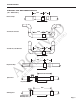
GENERAL INFORMATION The EX80-Series are electromagnetic insertion flow sensors for use in conductive liquids in pipe sizes 1” to 10” (25mm to 250 mm.) Lacking moving parts, they are well suited for applications with par ticulates in the fluid that are problematic for impellers or turbines. Other advantages are insensitivity to viscosity and tolerance for pulsating flows such as with air-driven diaphragm pumps. Fittings.
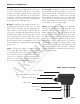
INSTALLATION DISTORTED FLOWS Faster Flow Causes Meter To Read High Meter Installation. After the meter fitting is installed in the pipeline, the meter can be installed in the fitting. After noting the direction of the flow arrow, press the meter into the fitting as far as it will go. Retain the meter in place by inserting the u-pin. The pin can be installed from either side. It may be necessary to rotate the probe back and forth slightly to start the pin into the slots on the probe.
INSTALLATION STRAIGHT PIPE RECOMMENDATIONS (X = diameter) 10X 5X AR CH IV ED Reduced Pipe 10X 5X 8/ 05 to 10 /0 6) Two Elbows In Plane 20X 5X es 6/ 2 Two Elbows, Out Of Plane 5X D at 20X Spiral Flow 30X (In cl ud es Expanded Pipe Propeller Meter 50X Swirling Flow Partially Open Butterfly Valve Page 3
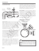
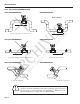
INSTALLATION FULL PIPE RECOMMENDATIONS NOT RECOMMENDED RECOMMENDED AR CH IV ED Ensures full pipe RECOMMENDED 6/ 2 8/ 05 to 10 NOT RECOMMENDED /0 6) Allows air pockets to form at sensor Keeps pipe full at sensor at es Post-valve cavitation can create air pocket RECOMMENDED (In cl ud es D NOT RECOMMENDED Air can be trapped Allows air to bleed off Caution: These flow sensors are not recommended for installation downstream of the boiler feedwater pump where installation fault may expo
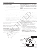
ELECTRICAL CONNECTIONS General Electrical Guidelines: Reverse Flow Output: Reverse flow output is available as an option. This open-collector isolated output does not supply power. It functions like a polarity-sensitive switch closure. Note: This output is limited to 6 mA at 30 Vdc maximum. • Whenever possible avoid running control cables in the same conduit with AC power. • Using shielded cable, be sure that one end is grounded.
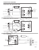
CONNECTIONS DIAGRAMS Counter or PLC + _ 12 - 24 Vdc Power + _ Forward Output Counter or PLC Digital Input Max. 6 mA, 30 Vdc Max. 6 mA 30 Vdc Reverse Output (Option-15 only) EX Series AR CH IV ED *See Dual FT420 Diagram for an example of bidirectional connections.
CONNECTIONS DIAGRAMS FT420 Display and Proportional Feed _ 24 Vdc Power + FT420 Sensor Input Power + _ Pulse Scaled + S _ Forward Output + _ + _ + _ Reverse Output (Option-15 only) AR CH IV ED + _ To Proportional Feed Metering Pump EX Series Pulse Pass-Thru /0 6) Power 4-20mA *See Dual FT420 Diagram for an example of bidirectional connections.
CONNECTIONS DIAGRAMS DL75 DATA LOGGER DL75 Sensor Input Power Forward Output AR CH IV ED Reverse Output (Option-15 only) EX Series 6) *See Dual FT420 Diagram for an example of bidirectional connections.
OPERATION & Maintenance Zero Adjustment. When the EX81 or 82 is powered up and there is no flow, there should be no output pulses (or, if connected to the FT420, flow rate should read “0”). If there are pulses it may be necessary to adjust the flow meter under no-flow conditions after it has been installed. This should only be done if the indicated flow is low, near the lower cutoff. Status LED 1 2 3 - 4 + 5 - Calibration (“K-factor”).
TROUBLESHOOTING Probable Cause Try... No pulse output Pipe not full Check Plumbing Below minimum flow cutoff Check the Presence of Flow LED (see pg.