
Manual


Page 5
Grounding Guidelines:
• For best results, use a good quality earth ground,
such as metallic water piping, or a stake driven
into the ground.
• If the flow sensor is installed in metallic piping, for
optimum grounding clamp wires to the piping a
short distance to either side of the flow sensor
using hose-type clamps. Connect these wires to
the earth ground and to one of the housing screws.
General Electrical Guidelines:
• Whenever possible avoid running control cables
in the same conduit with AC power. Use shielded
control cable where this type of installation is
necessary.
• If using shielded cable, be sure that one end is
grounded
• Avoid routing flow sensor cables in close proximity
to a variable frequency drive.
• Recommended power and output wiring is 18-22
AWG control cable, shielded if the run length is
more than 18 feet (6 meters).
• Recommended voltage is 12-24 VDC. Note that
unregulated power supplies can vary from
nameplate voltage by a considerable amount.
When in doubt, use a regulated power supply.
See the Connections diagrams on the following pages, for
the appropriate terminals.
Power: A 12 - 24 Vdc power supply which is capable of
at least 250 mA current output is needed.
Pulse Output: This open-collector isolated output does
not supply power. It functions like a polarity-sensitive switch
closure. It reaches a maximum of 500 Hz at the maximum
flow rate of 20 feet/second. This pulse is generated in
both forward and reverse flow directions (see “Direction”
below).
Note:
This output is limited to 5 mA at 30 Vdc
maximum.
Direction Indicator: This output is switched by a solid
state relay, which is not polarity sensitive. It is “off” (open)
when flow is in the forward direction and “on” (closed)
when flow is in the reverse direction.
Note:
this output is
limited to 100 mA at 150 Vdc maximum.
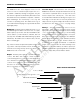
ELECTRICAL CONNECTIONS
GROUNDING DIAGRAM
Ground To
Metallic Pipe
Earth
Ground
Hose Clamp
ARCHIVED
(Includes Dates 6/14/04 to 5/05)