
User guide

EX110/210 INSTALLATION
Fitting Installation. EX110/210 adapters mate with a 1-1/2” female
NPT pipe thread adapter tting. Any tting that provides the matching
NPT female thread may be used. Installation procedure compensates
for tting height differences. Cut a minimum 1-3/4” hole in the pipe. If
possible, measure the wall thickness and write it down for use in depth
setting. Then install the threaded tting (saddle, weldolet, etc.) on the
pipe.
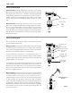
Meter Installation. Loosen the compression nut so that the adapter
slides freely. Pull the meter fully upward and nger-tighten the compres-
sion nut. Using a thread sealant, install the adapter in the pipe tting.
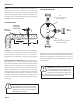
Do not overtighten. Now loosen the compression nut, lower the meter
to the appropriate depth setting (see diagram and instructions that fol-
low). Be sure ow is in the direction of the arrow on the housing. Tighten
compression nut fully.
EX150/250 INSTALLATION
‘Hot tap’ EX meters are designed so they can be installed and serviced
without depressurizing the pipe.
Fitting Installation. The EX150 and 250 adapters mate with a 2” FNPT
threaded tting for compatibility with the 2” isolation valve. Any tting
that provides matching NPT female thread may be used. The installation
procedure compensates for differences in tting height.
If initial installation is performed on an unpressurized pipe, cut a
minimum 1-3/4” hole in the pipe. If possible, measure the wall thickness
and write it down for use in depth setting. Then install the threaded tting
(saddle, weldolet, etc.) on the pipe.
If it is necessary to do the initial installation under pressure, any standard
hot tap drilling machine with 2” NPT adapter, such as a Transmate or a
Mueller, can be used. Ordinarily, it is not necessary to use an installation
tool, due to the small diameter tube the meter can be installed by hand
at all but the highest pressures.
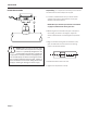
Meter Installation. Remove the sensor unit from the valve assembly.
Using a thread sealant, install the valve assembly on the pipe tting. If
the initial installation is a pressure (“hot”) tap, remove the 1-1/2” x 2”
adapter bushing at the back of the valve. Thread the tapping machine
on, open the valve, and tap using a minimum of 1-3/4” or maximum
1-7/8” cutter. After retracting the machine and closing the valve, reinstall
the ow sensor. When the sensor is secure, open the valve and adjust
depth setting (see diagram and instructions that follow). Be sure ow is
in the direction of the arrow on the housing. Tighten locking collar and
compression nut fully.
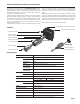
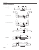
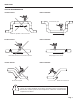
Compression nut
Adapter mates
with
FNPT
threads
Compression nut
2” adapter removes
to mount hot-tap
machine
Full-port 2” ball
valve allows sensor
removal
Mates with 2”
FNPT threads
EX150/250 Sensor
Removal
INSTALLATION
Page 3
Locking collar