
User guide

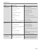


Min 0.28
Max 20.0
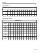
FLOW RATES (IN GALLONS PER MINUTE)
Feet Per
Second
NOMINAL PIPE SIZE
3” 4” 6” 8” 10” 12” 14” 16” 18” 20” 24” 30” 36” 48”
6 11 25 44 69 99 134 175 222 274 395 617 888 1580
440 783 1,762 3,133 4,895 7,050 9,596 12,533 15,863 19,584 28,200 44,064 63,452 112,804
OPERATION & MAINTENANCE
Page 12
Filtering. The software of the EX100/200-Series lters out
electrical noise and averages sudden variations in the ow
to smooth the output. It takes a matter of seconds for the
ow sensor to get up to full output when it is powered up or
when ow begins.
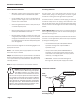
Electrode Coating. Grease or other adhering, non-conductive
materials can stop ow detection if the electrodes become
heavily coated. To clean the electrodes, remove the sensor
from the pipe and gently scrub the electrodes (three silver
bumps) on the reading face of the ow sensor. A mild soap
(dishwashing liquid for example) can be used to aid the
cleaning process.
Calibration (“K-Factor”). In order to properly process pulses
from the ow sensor, a number must be entered into the
control to which the sensor is connected. This number,
called the K-factor, is the number of pulses the sensor puts
out per unit of uid passing through the pipe. It is normally
provided for Seametrics sensors in pulses per gallon, and
can be ascertained by using the “K-Factor Calculator” on the
Seametrics website. These numbers are based on extensive
testing, which has shown close agreement among different
EX sensors in the same installation. Typically, most K-factor
error can be attributed to installation variables, such as depth
setting and tting conguration.
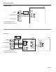
To perform the adjustment, after determining that there is a
full pipe with no ow, short between the two pins marked “Zero
Adjust”. A red LED light will come on for approximately 50 sec-
onds and then go out. The zero adjustment is completed.
Minimum Flow. As with any other ow sensor, there is a rate
below which the EX100-Series sensor cannot read. Check
the table below for the minimum ow rate detectable by the
sensor for a given pipe size.
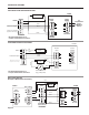
Presence of Flow Indication. To assist in troubleshooting,
the “Status LED” has two blinking modes in normal operation.
When there is no flow detectable by the meter (below
minimum threshold) the LED blinks every 8.0 seconds. When
there is detectable ow, the same indicator blinks every 3.0
seconds (Pulses are being output when indicator is blinking
every 3 seconds).
Zero Adjustment. When the EX100/200-Series meter is pow-
ered up and there is no ow, there should be no output pulses
(or, if connected to the FT420, ow rate should read “0”). If
there are pulses, it may be necessary to adjust the ow meter
under no-ow conditions after it has been installed. This should
only be done if the indicated ow is low, near the lower cutoff.
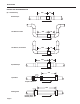
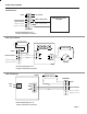
30Vdc
Max. 6mA
-
+
-
+
12-24Vdc
3 4 5 6 2 1
Power
Forward
Output
Status
LED
Zero
Adjust
Pins
Zero
Adjust
Pins
Status
LED
Using the K-Factor Calculator:
1) Go to the Seametrics webpage, EX K-factor calculator
(http://www.seametrics.com/node/223)*
2) Select your meter
3) Choose units
4) Input external pipe diameter (measure) and wall
thickness (measure, or look-up in Table 2 on page 5
of this manual)
5) Press Calculate to determine your K-factor
(NOTE: Dimension D is also calculated.)
6) Enter your K-factor into your controller
*For pipe sizes larger than 50”, please consult factory.