EX100/200-Series EX110 EX210 EX150 EX250 ISO 9 0 0 1 : 2 0 0 8 CERTIFIED COMPANY EX100/200-SERIES INSERTION MAGNETIC FLOW METER INSTRUCTIONS INSERTION MAGNETIC FLOW METER INSTRUCTIONS
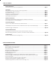
TABLE OF CONTENTS General Information General Information, Features, Specifications.................................................................................................. Page 1 Installation Piping, Distorted Flows, Immersion, Positioning the Meter............................................................................. Page 2 Fitting Installation, Meter Installation................................................................................................................
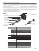
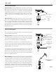
GENERAL INFORMATION, FEATURES and SPECIFICATIONS The complete lack of moving parts of the EX100/200-Series insertion flow sensor is the source of its reliability. Brass and stainless steel models withstand a variety of temperature, pressure, and chemical conditions. The EX-Series has no rotor to stop turning in dirty water and there are no bearings to wear out. A rapidly reversing magnetic field is produced in the lower housing.
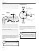
INSTALLATION Piping. For best results, the EX sensor should be installed with at least ten diameters of straight pipe upstream and five downstream. Certain extreme situations such as partially-opened valves are particularly difficult and may require more straight diameters upstream (see page 6 for straight pipe recommendations).
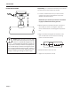
INSTALLATION EX110/210 INSTALLATION Fitting Installation. EX110/210 adapters mate with a 1-1/2” female NPT pipe thread adapter fitting. Any fitting that provides the matching NPT female thread may be used. Installation procedure compensates for fitting height differences. Cut a minimum 1-3/4” hole in the pipe. If possible, measure the wall thickness and write it down for use in depth setting. Then install the threaded fitting (saddle, weldolet, etc.) on the pipe. Meter Installation.
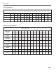
INSTALLATION Depth Setting. It is important for accuracy that the sensor be inserted to the correct depth into the pipe. PROPER DEPTH SETTING 1. In Table 1, find Dimension C for your sensor model and pipe size. Subtract wall thickness of your pipe (Table 2) to find Dimension D. "D" NOTE: When you calculate your K-factor as described on page 12, Dimension D will be given also. 2.
INSTALLATION TABLE 1: DIMENSION “C” NOMINAL PIPE SIZE 3” 4” 6” 8” 10” 12” 14” 16” 18” 20” 24” 30” 36” EX110 10.04 9.93 9.69 9.46 9.22 8.99 8.75 8.52 8.28 8.05 7.58 6.87 6.17 EX210 15.04 14.93 14.69 14.46 14.22 13.99 13.75 13.52 13.28 13.05 12.58 11.87 11.17 EX150 17.04 16.93 16.69 16.46 16.22 15.99 15.75 15.52 15.28 15.05 14.58 13.87 13.17 EX250 21.04 20.93 20.69 20.46 20.22 19.99 19.75 19.52 19.28 19.05 18.58 17.87 17.
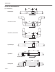
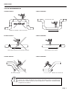
INSTALLATION STRAIGHT PIPE RECOMMENDATIONS (X = diameter) 10X 5X Reduced Pipe 10X Two Elbows In Plane Two Elbows, Out Of Plane 5X 20X 5X 20X 5X Expanded Pipe 30X Spiral Flow Propeller Meter 50X Swirling Flow Page 6 Partially Open Butterfly Valve
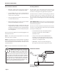
INSTALLATION FULL PIPE RECOMMENDATIONS Possible Problem Better Installation Ensures full pipe Allows air pockets to form at sensor Possible Problem Better Installation Post-valve cavitation can create air pocket Possible Problem Keeps pipe full at sensor Better Installation Air can be trapped Allows air to bleed off Caution: These flow sensors are not recommended for installation downstream of a boiler feedwater pump where installation fault may expose the flow sensor to boiler pressure and tem
ELECTRICAL CONNECTIONS General Electrical Guidelines: • Whenever possible avoid running control cables in the same conduit with or bundled with AC power. • Using shielded cable, be sure to connect shield to ground at power supply end of the cable. Do not connect other end of shield. • Avoid routing flow sensor cables in close proximity to a variable frequency drive. • Recommended power and output wiring is shielded twisted pair 18-22 AWG control cable. • Recommended voltage is 12-24 Vdc.
CONNECTIONS DIAGRAMS COUNTER OR PLC + 12 - 24 Vdc Power _ + Forward Output _ Max. 6 mA, 30 Vdc Reverse Output + (Option -15 only) _ Max. 6 mA 30 Vdc COUNTER OR PLC DIGITAL INPUT (open collector) EX-SERIES *See Dual FT420 Diagram for an example of bidirectional connections.
CONNECTIONS DIAGRAMS FT420 DISPLAY AND PROPORTIONAL FEED _ Power + _ 24 Vdc Power + FT420 Sensor Input Black Pulse Scaled + S _ Green Forward Output + _ White + _ + _ Red Reverse Output + (Option-15 only) _ To Proportional Feed Metering Pump + _ Black EX-SERIES Pulse Pass-Thru Power 4-20mA *See Dual FT420 Diagram for an example of bidirectional connections.
CONNECTIONS DIAGRAMS DL76 DATA LOGGER DL76 Red Energía de Black 12-24 Vdc Power Sensor Input Green Forward Output White Reverse Output (Option-15 only) *See Dual FT420 Diagram for an example of bidirectional connections.
OPERATION & MAINTENANCE Zero Adjustment. When the EX100/200-Series meter is powered up and there is no flow, there should be no output pulses (or, if connected to the FT420, flow rate should read “0”). If there are pulses, it may be necessary to adjust the flow meter under no-flow conditions after it has been installed. This should only be done if the indicated flow is low, near the lower cutoff.
TROUBLESHOOTING Problem Probable Cause Try... No pulse output Unit not grounded Connect to earth ground Below minimum flow cutoff Check the Presence of Flow LED (see p.
S e am e trics In c o r po r at e d • 1 9 0 2 6 7 2 n d A ven ue South • Ken t, Washi n g ton 98032 • USA ( P ) 2 5 3 . 8 7 2 . 0 2 8 4 • ( F ) 2 5 3 . 8 7 2 . 0 285 • 1. 800. 975. 8153 • w w w . seametr i cs.