
Manual
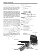
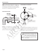
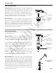
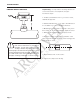
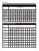

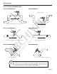

TABLE OF CONTENTS
General Information
Specifications, Parts Diagram ...................................................................................................... Page 1
Installation
Piping, Distorted Flows, Immersion, Positioning the Meter ........................................................ Page 2
Fitting Installation, Meter Installation........................................................................................... Page 3
Proper Depth Setting ................................................................................................................... Page 4
Table 1: Dimension “C”, Table 2: Pipe Wall Thickness ..................................................................... Page 5
Straight Pipe Recommendations .................................................................................................. Page 6
Full Pipe Recommendations................................................................................................ Page 7
Electrical Connections
General Electrical Guidelines, Power, Forward Flow Output, Reverse Flow Output,
Grounding Guidelines, Grounding Diagram ..................................................................................... Page 8
Connections Diagrams
Counter or PLC, A055 4-20 mA Output, FT520 Controller ................................................................. Page 9
FT420 Display and Proportional Feed, FT420 & 4-20 mA Output, FS30 Flow Switch ........................ Page 10
DL75 Data Logger, FT420/DL75, Dual FT420 Displays
(example of bidirectional connections) .......................................................................................... Page 11
Operation & Maintenance
Zero Adjustment, Minimum Flow, Presence of Flow Indication, Filtering,
Electrode Coating, Calibration (“K-Factor”) ...................................................................................Page 12
Flow Rates in Gallons Per Minute, EX Series K-Factor Char t ............................ Page 13
Troubleshooting
Problems, Probable Causes and Things to Try .................................................................................... Back
TABLES, DIAGRAMS & CHARTS
Parts Diagram ......................................................................................................................... Page 1
Distorted Flows, Positioning the Meter ............................................................................... Page 2
EX101/201, EX115/215, Sensor Removal ............................................................................... Page 3
Proper Depth Setting .................................................................................................................
Page 4
Table 1: Dimension “C”, Table 2: Pipe Wall Thickness .............................................................. Page 5
Straight Pipe Recommendations .......................................................................................... Page 6
Full Pipe Recommendations .................................................................................... Page 7
Grounding Diagram ........................................................................................................................ Page 8
Connection Diagrams: Counter or PLC, A055 4-20 mA Output, FT520 Controller ................................. Page 9
Connection Diagrams: FT420 Display and Proportional Feed, FT420 & 4-20 mA Output, FS30 Flow Switch
....... Page 10
Connection Diagrams: DL75 Data Logger, FT420/DL75, Dual FT420 Displays (example of bidirectional connections)
......... Page 11
Zero Adjustment ......................................................................................................................... Page 12
Flow Rates in Gallons Per Minute, EX Series K-Factor Chart ........................................................... Page 13
Troubleshooting Problems, Probable Causes and Things to Try ............................................................. Back
ARCHIVED
(Includes Dates 5/05 to 9/06)