EX100/200 Series 9/ 06 ) AR CH IV ED (In cl ud EX115 EX215 es D at es 5/ 05 to EX101 EX201 The Leader in Flow Meter Value.
Table of Contents General Information Specifications, Parts Diagram ...................................................................................................... Page 1 Installation Piping, Distorted Flows, Immersion, Positioning the Meter ........................................................ Page 2 Fitting Installation, Meter Installation........................................................................................... Page 3 Proper Depth Setting ..................................
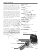
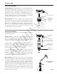
GENERAL INFORMATION The complete lack of moving parts of this insertion flow sensor is the source of its reliability. There is no rotor to stop turning in dirty water and there are no bearings to wear out. Brass, stainless, and PVC models withstand a variety of temperature, pressure, and chemical conditions. Reverse flow output and submersibility are optional. SPECIFICATIONS Power 12 – 24 Vdc, 250 mA max Flow RaNGE 0.2 – 20 ft/sec FITTING SIZE EX101/201B/S: 1.
INSTALLATION Piping. For best results, the EX sensor should be installed with at least ten diameters of straight pipe upstream and five downstream. Certain extreme situations such as partially-opened valves are particularly difficult and may require more straight diameters upstream.
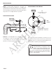
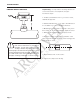
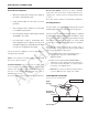
INSTALLATION EX101/201 INSTALLATION Fitting Installation. EX101/201 sensors come with a male NPT pipe thread adapter fitting (brass and stainless: 1 1/2”; PVC: 2”). Any fitting that provides the matching NPT female thread may be used. Installation procedure compensates for fitting height differences. Cut a minimum 1-3/4” hole in the pipe. If possible, measure the wall thickness and write it down for use in depth setting. Then install the threaded fitting (saddle, weldolet, etc.) on the pipe.
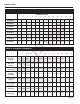
INSTALLATION Depth Setting. It is important for accuracy that the sensor be inserted the correct depth into the pipe. Follow these steps: PROPER DEPTH SETTING 1. In Table 1, find Dimension C for your sensor model, material and pipe size. "D" 2. Subtract wall thickness of your pipe to find Dimension D. Use Table 2 if you do not know the thickness. AR CH IV ED 3.
INSTALLATION Table 1: Dimension “C” Nominal Pipe Size 4” 6” 8” 10” 12” 14” 16” 18” 20” 24” 30” 36” EX101B/S 10.04 9.93 9.69 9.46 9.22 8.99 8.75 8.52 8.28 8.05 7.58 6.87 6.17 EX101PVC 12.04 11.93 11.69 11.46 11.22 10.99 10.75 10.52 10.28 10.05 9.58 8.87 8.17 EX201B/S 15.04 14.93 14.69 14.46 14.22 13.99 13.75 13.52 13.28 13.05 12.58 11.87 11.17 EX201PVC 17.04 16.93 16.69 16.46 16.22 15.99 15.75 15.52 15.28 15.05 14.58 13.87 13.17 EX115B/S 17.
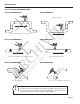
INSTALLATION STRAIGHT PIPE RECOMMENDATIONS (X = diameter) 10X 5X AR CH IV ED Reduced Pipe 10X 5X 5X 5X (In cl ud Expanded Pipe 20X es D at es 5/ 05 20X Two Elbows, Out Of Plane to 9/ 06 ) Two Elbows In Plane 30X Spiral Flow Propeller Meter 50X Swirling Flow Partially Open Butterfly Valve Page 6
INSTALLATION FULL PIPE RECOMMENDATIONS NOT RECOMMENDED RECOMMENDED AR CH IV ED Ensures full pipe 9/ 06 ) Allows air pockets to form at sensor RECOMMENDED es 5/ 05 to NOT RECOMMENDED Keeps pipe full at sensor es RECOMMENDED (In cl ud NOT RECOMMENDED D at Post-valve cavitation can create air pocket Air can be trapped Allows air to bleed off Caution: These flow sensors are not recommended for installation downstream of the boiler feedwater pump where installation fault may expose the
ELECTRICAL CONNECTIONS General Electrical Guidelines: Reverse Flow Output: Reverse flow output is available as an option. This open-collector isolated output does not supply power. It functions like a polarity-sensitive switch closure. Note: This output is limited to 6 mA at 30 Vdc maximum. • Whenever possible avoid running control cables in the same conduit with AC power. • Using shielded cable, be sure that one end is grounded.
CONNECTIONS DIAGRAMS Counter or PLC + Power _ 12 - 24 Vdc + Forward Output _ Max. 6 mA, 30 Vdc Reverse Output + _ (Option-15 only) Max. 6 mA 30 Vdc Counter or PLC Digital Input AR CH IV ED EX Series *See Dual FT420 Diagram for an example of bidirectional connections.
CONNECTIONS DIAGRAMS FT420 Display and Proportional Feed _ + 24 Vdc Power FT420 Sensor Input Power + _ Pulse Scaled + S _ Forward Output + _ To Proportional Feed Metering Pump + _ + _ Reverse Output + (Option-15 only) _ AR CH IV ED + _ EX Series Power 4-20mA ) *See Dual FT420 Diagram for an example of bidirectional connections.
CONNECTIONS DIAGRAMS DL75 DATA LOGGER DL75 Sensor Input Power Forward Output AR CH IV ED Reverse Output (Option-15 only) EX Series *See Dual FT420 Diagram for an example of bidirectional connections.
OPERATION & MAINTENANCE Zero Adjustment. When the EX100/200 Series meter is powered up and there is no flow, there should be no output pulses (or, if connected to the FT420, flow rate should read “0”). If there are pulses it may be necessary to adjust the flow meter under no-flow conditions after it has been installed. This should only be done if the indicated flow is low, near the lower cutoff. Calibration (“K-Factor”).
OPERATING CHARTS MINIMUM and maximum flow rates in gallons per minute Nominal Pipe Size 3” 4” 6” 8” 10” 12” 14” 16” 18” 20” 24” 30” AR CH IV ED Feet Per Second 4.5 8 18 31 49 70 96 125 159 196 282 (20.0) 440 783 1762 3133 4895 7050 9596 12533 15863 19584 28200 440 635 44064 63452 EX Series K-factors for various pipe sizes 6” 8” PVC/Steel Sch. 40 70.397 40.985 18.130 10.497 6.674 PVC/Steel Sch. 80 78.748 45.360 20.084 11.495 7.
TROUBLESHOOTING Probable Cause Try... No pulse output Unit not grounded Connect to earth ground Below minimum flow cutoff Check the Presence of Flow LED (see pg.