
User guide
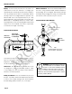


The complete lack of moving parts of this insertion flow
sensor is the source of its reliability. There is no rotor to
stop turning in dir ty water and there are no bearings to
wear out. A rapidly reversing magnetic field is produced
in the lower housing, and as the fluid moves through this
field a voltage is generated. This tiny voltage is measured
and translated into a frequency signal which is proportional
to flow rate. This square wave signal can be sent directly
to a PLC or other control, or can be converted using any of
the SeaMetrics family of indicators and convertors.
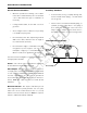
A modular system of electronics can be attached directly
to the flow sensor, or remotely mounted. SeaMetrics
currently offers four systems: The FT420 provides full
indication of rate and total, plus 4-20 mA output. The
AO55 provides blind 4-20 mA output, the PD10 divides
the pulse frequency, and the FS30 can be used for a
precise setpoint flow switch.
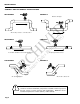
The installation fitting of the EX sensor is standard male
NPT, and can be directly threaded into ordinary saddles or
threaded weld fittings. The EX115 and 215 include an
isolation valve, allowing hot-tap installation, or installation
and removal under pressure. The standard isolation valve
is bronze, but a 316 stainless steel valve is available as
an option if needed.
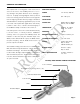
GENERAL INFORMATION
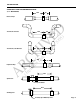
EX100/200 SERIES PARTS DIAGRAM
Housing Screw (connect ground to one)
Shaft
Cover or Module
Cable-Seal Strain Relief
Lower Housing
Sensor
Threaded Adaptor
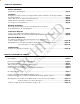
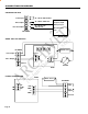
POWER 12 - 24 Vdc, 250 mA
FLOW RANGE 0.2 – 20 ft/sec
INSTALLATION
FITTING SIZE EX101, 201: 1.5” MNPT
EX115, 215: 2” MNPT
TEMPERATURE Ambient: 0 – 180 F
Fluid: 32 – 212 F
PRESSURE 200 psi
MINIMUM CONDUCTIVITY 20 microsiemens/cm
CALIBRATION ACCURACY 1% of full scale
OUTPUT Square wave pulse,
Opto isolated,
500 Hz @ 20 ft/sec
BI-DIRECTIONAL Direction output,
Opto isolated
EMPTY PIPE DETECTION Software, defaults to
zero flow
SPECIFICATIONS
Page 1
ARCHIVED
(Includes Dates Before 5/05)