
User guide
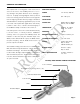
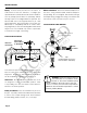

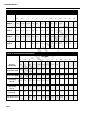
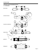
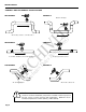
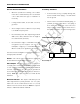
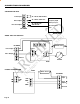

TABLE OF CONTENTS
General Information
Specifications, Parts Diagram ...................................................................................................... Page 1
Installation
Piping, Distorted Flows, Immersion, Fitting Installation, Meter Installation, Positioning the Meter ........ Page 2
Proper Depth Setting ................................................................................................................... Page 3
Table 1: Dimension “C”, Table 2: Pipe Wall Thickness ..................................................................... Page 4
Straight Pipe Recommendations (examples) .................................................................................. Page 5
Correct and Incorrect Installations ................................................................................................ Page 6
Electrical Connections
General Electrical Guidelines, Power, Pulse Output, Direction Indicator,
Grounding Guidelines, Grounding Diagram ..................................................................................... Page 7
Connections Diagrams
Counter or PLC, A055 4-20 mA Output, FT520 Controller ................................................................. Page 8
FT420 Display and Proportional Feed, FT420 & 4-20 mA Output, FS30 Flow Switch ........................... Page 9
Operation & Maintenance
Zero Adjustment, Minimum Flow, Filtering, Electrode Coating, K-Factor,
Location of K-Factor Diagram ....................................................................................................... Page 10
Operating Charts: Flow in Gallons Per Minute at Various Velocities - Schedule 40 Pipe ..................... Page 11
EX Series K-Factors for Various Pipe Sizes ....................................................... Page 11
Troubleshooting
Problems, Possible Causes, Things to Try .................................................................................... Page 12
TABLES, DIAGRAMS & CHARTS
Parts Diagram ............................................................................................................................... Page 1
Distorted Flows Diagram, Positioning the Meter ............................................................................... Page 2
Proper Depth Setting ....................................................................................................................
Page 3
Table 1: Dimension “C”, Table 2: Pipe Wall Thickness ....................................................................... Page 4
Straight Pipe Recommendations (examples) ................................................................................... Page 5
Correct and Incorrect Installations (examples and explainations) ...................................................... Page 6
Grounding Diagram ........................................................................................................................ Page 7
Counter or PLC, A055 4-20 mA Output, FT520 Controller .................................................................. Page 8
FT420 Display and Proportional Feed, FT420 & 4-20 mA Output, FS30 Flow Switch ............................. Page 9
Operating Charts: Flow in Gallons Per Minute at Various Velocities - Schedule 40 Pipe ....................... Page 11
EX Series K-Factors for Various Pipe Sizes ........................................................ Page 11
Troubleshooting Problems, Possible Causes, Things to Try ............................................................. Page 12
ARCHIVED
(Includes Dates Before 5/05)