EX100/200 Series AR CH IV ED (In cl ud es D at es Be fo re 5 /0 5) EX101 EX201 EX115 EX215 The Leader in Flow Meter Value.
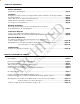
TABLE OF CONTENTS General Information Specifications, Parts Diagram ...................................................................................................... Page 1 Installation Piping, Distorted Flows, Immersion, Fitting Installation, Meter Installation, Positioning the Meter ........ Page 2 Proper Depth Setting ................................................................................................................... Page 3 Table 1: Dimension “C”, Table 2: Pipe Wall Thickness .......
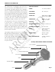
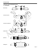
GENERAL INFORMATION SPECIFICATIONS POWER 12 - 24 Vdc, 250 mA FLOW RANGE 0.2 – 20 ft/sec INSTALLATION FITTING SIZE EX101, 201: 1.5” MNPT EX115, 215: 2” MNPT TEMPERATURE Ambient: 0 – 180 F Fluid: 32 – 212 F AR CH IV ED The complete lack of moving parts of this insertion flow sensor is the source of its reliability. There is no rotor to stop turning in dirty water and there are no bearings to wear out.
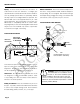
INSTALLATION Piping. For best results, the EX sensor should be installed with at least ten diameters of straight pipe upstream and five downstream. Certain extreme situations such as partially-opened valves are particularly difficult and may require more straight diameters upstream. The 101 and 201 sensors are supplied with a 1-1/2" male pipe thread fitting. The 115 and 215 sensors have a 2” NPT thread, for compatability with the 2” isolation valve.
INSTALLATION PROPER DEPTH SETTING Depth Setting. It is important for accuracy that the sensor be inserted the correct depth into the pipe. Follow these steps: 1. In Table 1, find the model of sensor which you have. Take Dimension C from this table for the pipe size. 2. Subtract wall thickness of your pipe to find Dimension D. Use Table 2 if you do not know the thickness. AR CH IV ED "D" 3.
INSTALLATION TABLE 1: DIMENSION "C" NOMINAL PIPE SIZE 2.5” 3” 4” 5” 6” 8” 10” 12” 16” 24” 30” 36” MX101 10.20 10.12 10.03 9.86 9.69 9.52 9.18 8.84 8.50 7.82 — — — MX201 15.20 15.12 15.03 14.86 14.69 14.52 14.18 13.84 13.50 12.82 11.46 10.44 10.42 AR CH IV ED 2” 17.24 17.14 17.04 16.84 16.74 16.54 16.14 15.84 15.54 14.84 MX215 - - - 20.89 20.69 20.49 20.19 19.89 19.49 18.79 — — 5) MX115 16.49 15.39 fo re 5 /0 17.
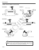
INSTALLATION STRAIGHT PIPE RECOMMENDATIONS (x = diameter) 10X Reduced Pipe 5X D E V I H C R A Two Elbows In Plane 5X ef o re 5/ 05 ) 10X 20X 5X at e sB Two Elbows, Out Of Plane (In cl ud Expanded Pipe 5X es D 20X Spiral Flow 30X Propellor Meter 50X Swirling Flow Partially Open Butterfly Valve Page 5
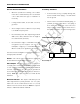
INSTALLATION CORRECT AND INCORRECT INSTALLATIONS CORRECT INCORRECT D E V I H C R A Ensures full pipe /0 CORRECT Be fo r e5 INCORRECT 5) Allows air pockets to form at sensor Post-valve cavitation can create air pocket CORRECT (In cl ud es INCORRECT D at es Keeps pipe full at sensor Air can be trapped Allows air to bleed off Caution: These flow sensors are not recommended for installation downstream of the boiler feedwater pump where installation fault may expose the flow sensor to bo
ELECTRICAL CONNECTIONS General Electrical Guidelines: Grounding Guidelines: Whenever possible avoid running control cables in the same conduit with AC power. Use shielded control cable where this type of installation is necessary. • If using shielded cable, be sure that one end is grounded • Avoid routing flow sensor cables in close proximity to a variable frequency drive.
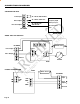
CONNECTIONS DIAGRAMS COUNTER OR PLC + 11 - 24 Vdc 250 mA max. _ Power Input Pulse Output + _ 11 - 24 Vdc 5 mA max. Frequency Input 25 hz per ft/sec 11 - 24 Vdc/Vac 100 mA max.
CONNECTIONS DIAGRAMS FT420 DISPLAY AND PROPORTIONAL FEED _ 24 Vdc Power + FT420 Sensor Input Power Input + _ Pulse Scaled + _ + S _ Pulse Output + _ To Proportional Feed Metering Pump + _ AR CH IV ED Direction Output + _ EX SERIES Pulse Pass-Thru 5) Power 4-20mA 24 Vdc Power + re 5 _ /0 FT420 DISPLAY AND 4-20 mA OUTPUT Sensor Input Pulse Scaled fo Be Power Input + _ + S _ Direction + _ + _ es Pulse Output + _ EX SERIES D at Unused _ ud es + FT420 + _ Pulse Pass-Th
OPERATION & MAINTENANCE When the EX100 Series Meter is powered up and there is no flow, there should be no output pulses (or, if connected to the FT420, flow rate should read “0”). If there are pulses... Zero Adjustment. In some cases it may be necessary to adjust the flow meter under no-flow conditions after it has been installed. AR CH IV ED To per form the adjustment, after determining that there is no flow, short between the two pins marked “Zero Adj.
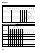
OPERATING CHARTS FLOW IN GALLONS PER MINUTE AT VARIOUS VELOCITIES: SCHED. 40 PIPE NOMINAL PIPE SIZE 2” 2.5” 3” 4” 5” 6” 8” 10” 12” 16” 24” 36” 38” 48” (0.2) 2.6 3.8 5.8 9.9 15.6 22.5 39 66.4 88 138 314 729 884 1409 (1.0) 10.5 14.9 23 39.7 62.4 90 156 246 349 551 1250 2910 3530 5640 AR CH IV ED Feet Per Second 52.3 74.6 115 198 312 450 780 1230 1740 2750 6270 14570 17670 28200 (10.
TROUBLESHOOTING Problem Probable Cause Try...