EM101 EM101 LOW FLOW MAGNETIC FLOWMETER INSTRUCTIONS LOW FLOW MAGNETIC FLOWMETER INSTRUCTIONS
Table of Contents General Information Features, Specifications, Flow Range ........................................................................................................... Page 1 Installation and Operation Mounting, Connections, Grounding, Display, Outputs, Mounting Diagrams ................................................... Page 2 Connections and Grounding Flow Meter, Display Board, Ideal Grounding with Metallic Piping, Standard Grounding ...............................
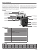
GENERAL INFORMATION The EM101 is a small electromagnetic low-flow flowmeter with chemically-resistant plastic wetted parts and platinum electrodes suitable for use with a variety of chemicals. Capable of measuring pulsating flows from diaphragm-type metering pumps, it is designed primarily for electrically-conductive chemical injection applications. The 1/4” and 3/8” sizes monitor maximum flows of 1 and 3 gallons per minute (or 4 and 11 L/min), respectively.
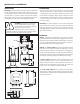
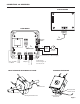
INSTALLATION and OPERATION INSTALLATION CONNECTIONS Mounting. Mount the display housing to a secure surface with screws or bolts. Remove the front cover to gain access to the mounting holes, directly under the front cover screws. Attach the flow meter to a secure surface using the foot bracket. Alternatively, the unit can be supported by the piping and the foot bracket removed. See mounting diagrams below. The meter ships with the coil activation and signal leads already connected to the display housing.
CONNECTIONS and GROUNDING DISPLAY BOARD To Sensor Display Cable + To Sensor (UNUSED) RED WHITE GREEN BLACK FLOW METER Power Supply - + Analog Device - + High Alarm Pulse Output Low Alarm Fuse, .
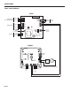
CONNECTIONS FT520 - Batch Control FT520 Pulse 1 RESUME COM BATCH Pulse 2 Relay 1 Batch Outputs Relay 2 NO COM NC NO COM NC Start/Stop Remote Controls + s1 – - s2 + Active Main power fuse 250mA part # 26926 AC Power Resume 5V 10V 4-20mA A P + – A B An Output Pulse Outputs (for metering pumps) 0-5 V or 0-10 V or 4-20 mA Jumpers Passive Line Neutral Ground Analog Switch Analog Header EM101 Display Cable To Display + (UNUSED) Power Supply - + Analog Device - + Page 4 High Al
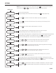
SETTINGS SET-UP. Use the instructions below to set up your control. Use the the next, and use the and SET key to move from one operation to keys as described to change settings within operations. DISPLAY This is the power-up display. Rate/total display (shows two seconds after power-up), Press Rate Tot SET to begin programming.
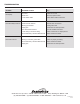
TROUBLESHOOTING Problem Probable Causes Try...