
User guide

0
9
8
7
6
5
4
3
2
1
0
9
8
7
6
5
4
3
2
1
0
9
8
7
6
5
4
3
2
1
0
9
8
7
6
5
4
3
2
1
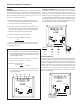
AO55
Frequency
Power
Sensor
4-20 mA
-
+
4-20 mA Device
(e.g. Pump, PLC,
Chart Recorder)
24-36 Vdc
Power Supply
(may be
included in
control unit)
Mechanical
Sensor
Red
White
Black
-
+
-
+
S
+
_
S
+
+
_
_
Magmeter
Terminal Block
AO55
Terminal
Block
Power
Forward
Output
24 Vdc
-
+
Wiring AO55 to
Mechanical Meter
Wiring AO55 to Magmeter
Green
White
(Either/Or)
LT-65200015-B
6/24/09
Seametrics Incorporated • 19026 72nd Avenue South • Kent, Washington 98032 • USA
(P) 253.872.0284 • (F) 253.872.0285 • 1.800.975.8153 • www.seametrics.com
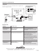
CONNECTIONS and TROUBLESHOOTING
TROUBLESHOOTING
CONNECTIONS
Problem
Probable Cause Try...
No analog signal at
reading device
Output stuck at 4 mA
mA signal does not
match ow rate
Break in current loop
Dead power supply
Reversed polarity
No frequency input from ow sensor
Inadequate voltage
Wrong frequency setting
Check if loop indicator light is on
Check multimeter voltage on power supply
Check polarity
Check if ow sensor rotor is turning freely
(mechanical meters only)
Check ow sensor connections
Check ow sensor polarity
Be sure terminal blocks are rmly plugged in
With ow sensor disconnected, use short wire
to repeatedly short between sensor “sig” and
“-” terminals. Output should rise.
Verify 3-second pulse output (EX meters only)
Check load vs. supply chart
Review setting procedure
Check multimeter voltage on power supply
The AO55 can be wired to either a mechanical meter or a magmeter. See
alternative congurations below.