AG1000 AG1000 IRRIGATION MAGMETER INSTRUCTIONS IRRIGATION MAGMETER INSTRUCTIONS ag1000 The Leader in Flow Meter Value.
Table of Contents General Information Specifications, Parts Diagram ...................................................................................................... Page 1 Installation and Electrical Connections Positioning the Meter, Piping Conditions, Electrical Connections, Electrical Noise Immunity .. Page Straight Pipe Recommendations.................................................................................................. Page Full Pipe Recommendations ...............................
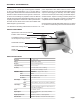
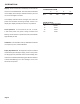
GENERAL INFORMATION The AG1000 is a spool-type electromagnetic flowmeter for use in irrigation applications in 4” to 10” pipe. With no moving parts, these meters have unobstructed flow and are resistant to wear from debris found in ground or surface water. There are no bearings or propeller to wear out. Minimal straight pipe requirements allow AG1000 meters to be used in piping configurations where there is little space between the meter and an elbow.
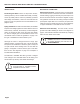
INSTALLATION AND ELECTRICAL CONNECTIONS INSTALLATION electrical connection Positioning the Meter. These are all-position meters, meaning that they can be installed horizontally, vertically, and in any radial position. If there is potentially a problem with sludge accumulation, vertical or horizontal with the register up may be preferred. See recommendations on pages 3 and 4. Electrical Connections. A current source of some kind at 12 to 24 VDC must be connected to the meter.
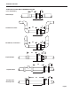
INSTALLATION STRAIGHT PIPE RECOMMENDATIONS (X = diameter) 1X 2X Reduced Pipe Two Elbows In Plane Two Elbows, Out Of Plane 1X 2X 1X 2X 1X 5X Expanded Pipe 5X 1X Propeller Meter 5X 1X Partially Open Butterfly Valve Page 3
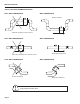
INSTALLATION FULL PIPE RECOMMENDATIONS NOT RECOMMENDED RECOMMENDED Ensures full pipe Allows air pockets to form at sensor NOT RECOMMENDED Post-valve cavitation can create air pocket NOT RECOMMENDED Air can be trapped RECOMMENDED Keeps pipe full at sensor RECOMMENDED Allows air to bleed off Caution: These flow sensors are not recommended for installation where temperature exceeds 120°F.
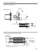
ELECTRICAL CONNECTIONS STANDARD CONNECTION Green ground wire, supplied For optimum performance, ground both ends of the meter to adjacent metal pipe Reliable Earth Ground Ferrite Bead, Digi-Key p/n 240-2076-ND .5 in.
OPERATION Display. There are two lines to the display, one for flow rate and one for accumulated total. The units used are indicated on the display. These are pre-ordered and factory set, and can not be changed in the field. FLOW RANGE IN GPM 4” 6” Min 12 32 Max 500 1200 If the display indicates letters and digits, the meter has power and should be functioning normally. If there is no display (the display is blank) the meter is not powered. Solar Operation.
TROUBLESHOOTING Problem Probable Cause Try...
19026 72nd Ave South, Kent, WA 98032 USA (P) 253.872.0284 (F) 253.872.0285 www.seametrics.com 1.800.975.