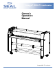
Image® 600-C Laminator Owner’s Operation Manual Image ® 600-C Laminator
TABLE OF CONTENTS TABLE OF CONTENTS ...................................................................................................................................................................2 INTRODUCTION................................................................................................................................................................................3 WORKSPACE / ELECTRICAL REQUIREMENTS .....................................................................................
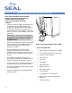
INTRODUCTION Thank you for purchasing a SEAL ® Image® 600-C Laminator. We have designed the SEAL Image 600-C to give you years of reliable service. As you become familiar with your laminator, you will appreciate the high quality of its production and the excellence in its engineering design. By following the guidelines for proper care and use of the laminator, you can depend on many years of trouble-free profitability from your investment.
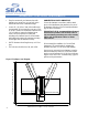
WORKSPACE / ELECTRICAL REQUIREMENTS • • Keep the area around your laminator clear with adequate space around it so you can feed, receive and trim mounted and/or laminated images. CONNECTING YOUR LAMINATOR Connect the laminator in accordance with the details given on the identification plate attached to the rear of the laminator. Refer also to the Technical Specifications page for more information. An area 15’ x 11’ (4.5m x 3.4m) is the smallest area recommended. We recommend a room size of 20’x 18’ (6.
ENVIRONMENT CONDITIONS The following environmental conditions are ideal for the best operation of the laminator. AMBIENT TEMPERATURE The best temperature for the laminator is between 50°F and 86°F (16°C and 30°C). Do not expose the laminator to direct sunlight as output quality may be affected. SURROUNDINGS Install the laminator in surroundings that are as clean and dust free as possible in order to obtain the highest quality output.
UNPACKING, SET-UP AND INSTALLATION ONLY SKILLED PERSONNEL SHOULD PERFORM INSTALLATION. READ AND COMPLY WITH ALL WARNINGS AND FOLLOW THE PROPER INSTALLATION PROCEDURES AND SAFETY GUIDELINES. • Take into account the weight of the laminator in its crate (1080 lb./490 kg shipping weight) when moving. Use equipment with which the weight can be safely lifted. The laminator is transported on a wooden pallet (skid).
UNPACKING, SET-UP AND INSTALLATION UNPACKING YOUR LAMINATOR • Remove the transport packing and the plastic shrink-wrap the laminator is wrapped in to avoid moisture penetration. • Remove the accessory kit package from the top of the laminator, which includes the necessary tools for installation/operation. • Remove the footswitch from the top of the laminator and remove the foam wrapped around it. Place the footswitch in a position that is accessible while feeding images.
IMPORTANT SAFEGUARDS SAFETY SYMBOLS USED ON THE LAMINATOR IMPORTANT! Read and make sure you understand these safety and operating guidelines. ROTATING PARTS: RISK OF INJURY CAUTION! Failure to use caution near rotating rollers could result in physical injury. Be careful that items such as loose clothing, long hair and jewelry do not become entangled in rotating parts. The laminator is equipped with photoelectric eyes to prevent contact with the rotating rollers.
SAFETY FEATURES The SEAL ® Image® 600-C Laminator is designed with safety and protective devices with the user’s safety of utmost consideration. However, following safe operating guidelines is still the responsibility of the operator. PHOTO ELECTRIC SAFETY EYES: HAND-OPERATED EMERGENCY STOP BUTTONS: LOCKING CABINETS: Emergency Stop buttons are located on the top of each of the cabinets for easy access. Once pressed, they immediately cease the laminator’s operation and raise the top roller.
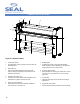
LAMINATOR FEATURES 2 3 4 6 1 8 7 4 5 5 Figure 3. Laminator Features 1. • Control panel system For independent control of pressure, roller activation and laminating speed. 2. • Shim Wheels (2) Dial-in roller height adjustment for fast and accurate roller nip setting, which adjusts for the thickness of the material to be processed 3. • 4. • 10 5. • Braking System A braking system with Lock Collars and adjustable Brakes for precise tension adjustment for the films and images.
FRONT CONTROL PANEL 1. Air Regulator Knob: Adjusts the downward pressure of the top roller. Turn clockwise to increase the pressure. 2. Air Pressure Gauge: Indicates the PSI reading for the downward pressure of the top main roller. The standard setting for the normal operation is 35-55 PSI. 3. Roller Up/Down Switch (Front, Top): Press UP to raise the roller. Press DOWN to lower the roller. Reset this switch (press UP, then DOWN) after pressing an Emergency Stop. 4.
CHECKING OPERATION After you are familiar with the control panel and its functions, check all operations. CHECK THE MOTOR AND FOOTSWITCH • Push the green Motor Switch UP, the switch will be illuminated and the rollers should rotate in the forward direction. • As you turn the speed control knob clockwise the speed of the roller rotation should increase. • Turning the speed control knob counter-clockwise should decrease the speed of the roller rotation.
S E T -UP AND OPERATION HOW TO SET THE SHIM WHEELS SHIM WHEEL SETTINGS • First, determine the thickness of the board that you will use for mounting. • You must first raise the top roller and then press down and turn both the shim wheels until the desired measurement corresponds with the thickness of board being used. Whenever you mount onto a board, etc., it is important to adjust the rollers to create a gap nearly equal to the thickness of the board being used.
S E T -UP AND OPERATION SETTING THE UNWIND BRAKE TENSION IMPORTANT! The brake tension greatly affects the smooth flow of the laminating film. • IMPORTANT! Make certain that you place the roll of film on the unwind shaft so that the material will feed with the adhesive side facing away from the rollers. Turning the unwind brake in a counter-clockwise direction increases the braking tension applied on the laminate. • • Turning the unwind brake in a clockwise direction decreases the braking tension.
S E T -UP AND OPERATION AUTO-RUN OPERATION • The continuous-run operation allows the user to start the roller rotation and adjust the roller speed by turning the Speed Control knob on the control panel. IMPORTANT! If the photoelectric eyes become blocked during continuous-run operation, the roller rotation will stop immediately.
FEEDING IMAGES BASIC STEPS TO FEEDING IMAGES NOTE: For good results, the process requires that the images be fed through correctly. • Make sure the leading edge of each image is flat all the way across or any wrinkles or creases in the image will show when laminated – perhaps even magnified. • A straight leading edge will aid in feeding in the image. • Feed the image into the laminator ensuring that the leading edge is parallel to the roller.
WEBBING FILMS WITH A RELEASE LINER (NORTH AMERICA) The following are the basic webbing procedures for webbing films with a release liner. It is important to follow the webbing instructions for films specific for your location. • Select films slightly wider than the image to allow for a border without film waste. A border of 1/8” to 1/4” (3 - 6mm) is adequate. • Load and center the films on top and bottom unwind shafts with the dull adhesive side facing out and the unwind brake tension released.
WEBBING FILMS WITH A RELEASE LINER (EUROPE & ASIA) The following are the basic webbing procedures for webbing films with a release liner: It is important to follow the webbing instructions for films specific for your location. • Select films slightly wider than the image to allow for a border without film waste. A border of 1/8” to 1/4” (3 - 6mm) is adequate. • Load and center the films on top and bottom unwind shafts with the dull adhesive side facing out and the unwind brake tension released.
DECALING (PRESSURE- SENSITIVE) This process involves applying a cold pressure-sensitive over-laminate to the top and a cold pressure-sensitive mounting adhesive to the bottom of a graphic. This process can be used to create self-adhesive images (Decals) for mounting down onto various substrates. After performing this process, follow the Mounting Instructions in the manual to apply the decal to a substrate. It is important to follow the webbing instructions for films specific for your location.
MOUNTING This process involves mounting previously prepared decals onto a substrate. No films or adhesives are required for this process. • TO MOUNT DECALS ONTO A SUBSTRATE • If the board is accidentally sent in too far at first, the release liner will get caught and will be impossible to pull back. In this case, stop and raise the top roller and pull back until the liner can be pulled away. • The image must be held against the roller while the board feeds through to prevent wrinkles.
P R E -COATING BOARDS This process is used to coat substrates with a selfadhesive coating onto which images can be mounted. Images can then be mounted on the substrate. This same process is used to create a Sled (refer to Glossary). LAMINATOR SETTINGS: NOTE: When coating boards, ensure that the next board to be coated follows the previous board without any gaps.
APPLYING AN OVER-LAMINATE An Over-laminate with a release liner can be applied to your mounted prints, photographs or images on photographic papers. A Sled (refer to Glossary) is needed to support non-mounted prints during the laminating process. Non-mounted prints are placed face up on the sled and over-laminated as the sled passes through the rollers. Follow the same basic procedures for over-laminating mounted prints, eliminating the sled use.
G L O S S A R Y O F T E R MS DECAL: PRE-COATING: An image that has been laminated with a pressuresensitive film on top and with an adhesive backing. The process of coating a substrate with an adhesive mounting film onto which an image can be mounted. FILM: PRESS: A synonym for laminate. The material used in the laminating and encapsulating process. The amount of force in distance put on anything that passes between the top and bottom rollers.
PROCESS APPLICATION NOTES _______________________________________ ________________________________________ _______________________________________ ________________________________________ _______________________________________ ________________________________________ _______________________________________ ________________________________________ _______________________________________ ________________________________________ _______________________________________ _____________________________
PROCESS CONTROL SHEET Process: __________________________________ Application Use: ____________________________ Top Unwind: ______________________________ Bottom Unwind:____________________________ CONTROL PANEL SETTINGS NOTE: We recommend that you make a photocopy of this page. With each successfully run application, record the process and settings and a diagram of the webbing procedure. Keep the record so the application can be repeated at a later date.
CLEANING / MAINTAINING YOUR LAMINATOR CLEANING THE LAMINATOR • The laminator may be cleaned with a lint-free cloth, lightly dampened with a mild soap and water solution. Do not use spray-on cleaners. Do not immerse any part of the laminator in water or other liquids. • Do not use an abrasive cleaner, which can damage the painted surfaces. • Do not allow water or liquids to enter the electrical circuits, which may cause personal injury and/or damage the equipment when power is applied.
PERIODIC MAINTENANCE SHEET GREASE BEARINGS CHAIN T ENSION ADJUSTMENT / OIL CHAIN ** DRAIN WATER (AIR FILTER)*** SAFETY CHECK AFTER SERVICING NOTE: Enter dates of service and initials of service personnel. We recommend that you make a photocopy of this page, tape it to the inside of the cabinet door and use this to record dates that authorized safety or maintenance personnel perform these laminator maintenance procedures.
TROUBLESHOOTING GUIDE Problem Solution The laminator will not turn on. • Check if the power cable is plugged into the mains wall outlet. • Check that the Main Power Stand-by switch is ON. • Unplug the laminator and check the circuit breakers and fuses inside the left cabinet. Only authorized safety or maintenance personnel should do this. • Make sure the left side cabinet door is closed and the Door interlock is in the ON position.
SPARE PARTS LIST Please contact Technical Service for replacement parts. PART DESCRIPTION PART # PART DESCRIPTION PART # Air Compressor 225020 Clutch Drive O-ring 169007 Air Cylinder Kit 6008 Clutch Idler Kit 4002 Air Filter Kit 5507 Door Disconnect, 25 Amp 143020 Air Gauge Kit 50609 Fuse, 1.
TECHNICAL SPECIFICATIONS M ECHANICAL Dimensions (H x W x D) 78”w x 32”d x 50”h (198 cm x 81 cm x 127 cm) Net Weight 630 lbs. (286 kg) Shipping Weight (in crate) 1080 lbs. (490 kg) Roller Construction Two high release silicone-covered rollers Mechanical Requirements 2 CFM compressed air @ 100 psi, 0.25” (0.6 cm) ID flexible line PROCESS Max. Working Width 61” (155 cm) maximum Max. Roller Speed 10 fpm (3.1 mpm) Core Inner Diameter 3” (7.6 cm) Maximum Material Outside Diameter 8” (20.
LIMITED WARRANTY SEAL ® Graphics warrants to the original consumer purchaser that each new SEAL ® Image® Laminator, which proves defective in materials or workmanship within the applicable warranty period, will be repaired or, at our option, replaced without charge. Effective November 1st, 2002 the applicable warranty period for New Equipment shall be one year (parts), six months (labor and rollers) from date of purchase.
SEAL BRANDS TECHNICAL SERVICE SEAL BRANDS TECHNICAL SERVICE – EUROPE AND ASIA PACIFIC (For technical assistance & service) (For technical assistance & service) Tel: 1-800-486-6502 For UK: Tel: +44 1268 722 400 Fax: 1-800-966-4554 Fax: +44 1268 729 442 or +44 870 125 5798 For NL: Tel: +31 572 345 500 Fax: +31 572 345 501 SEAL BRANDS CUSTOMER SERVICE SEAL BRANDS CUSTOMER SERVICE – EUROPE AND ASIA PACIFIC (For information and placing orders) (For information and placing orders) Tel: 1-800-257-7