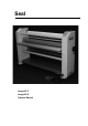
Seal Image 60 C Image 60 S Owners Manual
Contents Subject Page Contents Illustrations Limited Warranty on Seal Image Laminators Introduction Using this manual 2 3 4 5 5 Features and benefits of the Image 60C/S Safety information Safety features General information General use 7 9 10 13 13 Technical specification Identification Un-crating and moving the Image 60C/S Operating conditions Connecting to the electric supply 14 14 15 16 16 Main switch Control panel 60C Control panel 60S Control panel Emergency stop buttons 17 19 21 22 25 Emerge
Illustrations Subject Page Features and benefits of the Image 60C/S Working space Identification Wood blocks Main switch 6 12 14 15 17 Control panel Image 60C Control panel Image 60C when rotation of roller is active Control panel Image 60S Emergency stop button Emergency stop trip wire 18 19 20 25 25 Roller up/down and roller pressure Unwind brake Supply shaft Feed-in table Mounting / Dismounting image guide 26 28 29 30 30 Front take-up shaft Decaling (with liner) Decaling (without liner) Mounting
Limited Warranty on Seal Image Laminators Seal Graphics warrant to the original consumer purchaser that all new Seal Image Laminators that prove defective in materials or workmanship within the applicable warranty period will be repaired or, at our option, replaced without charge. The applicable warranty shall be one year from date of purchase. This warranty does not apply if it is found that at any time the equipment has not been used for its intended purpose.
Introduction Thank you for purchasing the IMAGE 60C/S laminator. It has been designed to give you years of reliable service. The IMAGE 60C/S brings a new level of simplicity and ease of use to image finishing. By following the guidelines outlined in this manual for proper care and maintenance, you can depend on receiving any years of trouble-free profitability from your investment.
Features and Benefits of the Image 60C/S 11 8 1 9 6 5 2 4 3 7 10 6
Features and Benefits of the Image 60C/S Image 60C: 1. Digital touch pad control-panel with LED indicators and preset settings for, 60C: speed, nipopening, pressure and additionally for the 60S, temperature. 2. Hand wheel for up and down movement of top roller. 3. Knob pre-pressure control for setting pre-pressure of top roller. 4. Swinging feed-in table for easy loading, with integrated Emergency Stop System. 5.
Safety Information The IMAGE 60C/S laminator is provided with safety equipment to promote safe machine operation. You should however take note of the following. Read and make sure you understand these safety and operating instructions. WARNINGS: Hot surfaces – Danger of getting injured by hot parts. Be careful with hot parts. The heated rollers can have a surface 0 0 temperature of up to 135 C (275 F). Do not touch the rollers.
Safety Features Emergency stop buttons There are two Emergency Stop buttons and they are located on top of the right and left cabinets of the laminator. They stop the rotation of the rollers and should only be used in case of an emergency. Emergency stop trip wire One emergency stop trip wire is located at the front side close to the bottom side of the laminator. The switch is installed at the right cabinet.
Safety Features The forward rotation of the rollers will stop when: The opto-electronic protective device in front of the main rollers is interrupted. NOTE: This does not happen when the combined slow mode and foot pedal function is used. An emergency stop button is pressed. The emergency stop trip wire is touched by foot or by hand. The feed-in table is turned out of its operating position. The stop button on the control panel is pressed. The foot pedal is pressed for a short moment.
General Information Minimum room length = 8 feet / 2.5 meter maximum board length 62 inch / 1575 mm 24 inch / 600 mm room length = 2x max. boarrd length + 27 inch / 68 cm roll of laminate maximum board length room width = 15 feet / 4.
General Information Power Sources – Only connect the laminator to the power supply specified on the identification label. Refer to the “Specifications” chapter in this manual for more information. Water and Moisture – Install an RCD (GFI in U.S.A.) in the buildings electrical supply if the laminator is used near water or in an area of high humidity. Environment – Use your laminator in the cleanest, most dust free environment possible to produce the highest quality output.
Technical Specification Maximum working width: Maximum roller width: Maximum roller nip opening: Maximum substrate thickness: Maximum roller speed: Maximum roller temperature (only top roller 60S) Core inner diameter Dimensions Net weight Shipping weight Power supply Power supply Maximum power consumption Maximum power consumption Dimensions roll to roll option 60C: 60S: 60C: 60S: 62 66 1 3/16 1 15 275 3 Width: 85 Depth: 27 Height: 56 950 1060 1N/PE 200 – 250 VAC 3N/PE 200 – 250 VAC inches inches inches
Un-crating and Moving The Image 60C/S Your Image 60C/S laminator is supplied in its own custom designed box with integral 4-way entry pallet and its wrapped in plastic film to prevent moisture penetration. WARNING: If lifting the pallet from the end the forklift must be fitted with extensions that support the whole length of the box. NOTE: If future transportation of the laminator is a possibility, the pallet, crate and securing bolts should be kept in safe place.
Operating Conditions Temperature 0 0 0 0 10 C - 50 C (50 F - 122 F) Do not expose the laminator to direct sunlight as output quality may be affected. Moisture 30% ~ 95% non-condensing Ideal humidity ~ 55% Dust Avoid a dusty environment because the films used on this laminator will attract dust and the output quality will be affected. Connection to the Electrical Supply In process of setting up your IMAGE 60C/S, the laminator will require to the electrical supply.
Main Switch The main electrical supply “ON/OFF” switch is located on the backside of the right cabinet.
Control Panel 1 11 2 3 12 13 6 14 4 5 15 7 8 16 9 10 Control panel Image 60 C 18
Control Panel Control panel 60 C No. Action or Indication 1. This LED indicates that the setting of the nip opening is showed in mm (SI Unit). 2. This LED indicates that the setting of the nip opening is showed in inches (Imperial). 3. The digital display shows the setting of the nip opening in mm or inches or when the start mode is activated, the current in Amps. 4. This LED indicates that the reverse function is activated. 5.
Control Panel 20 25 21 26 22 27 28 23 29 24 30 1 11 2 3 12 13 6 14 4 5 15 7 8 16 9 10 Control panel Image 60 S 20
Control Panel Control panel 60 S No. Action or Indication 0 20. This LED indicates that the set-point of the roller temperature is showed in C (degrees Celsius). 0 21. This LED indicates that the set-point of the roller temperature is showed in F (degrees Fahrenheit). 22. The digital display shows the set-point of the roller temperature. 23. Heater “ON” button. This switches on the heater of the top roller. 24. Heater “OFF” button. This switches off the heater of the top roller. 25.
Control Panel The laminators control panel is situated on the front right. The control panel of the 60C is divided into 2 sections, motor control section and display section. The control panel of the 60S is divided into 3 sections, motor control section, display section and heater control section. MOTOR CONTROL SECTION The rotation of the rollers is started as follows: 1. Set the machine for the necessary process as is prescribed by Seal Graphics. 2. Select the necessary mode to operate the machine.
Control Panel Foot pedal The foot pedal is connected by cable to the machine and has to be positioned at the floor in front of the laminator. The foot pedal can be used to rotate the rollers in forward mode or in slow (snail) mode. Keep the foot pedal pressed to operate the rollers. Release the foot pedal to stop rotation of the rollers.
Control Panel DISPLAY SECTION Left display shows roller nip setting or motor current. When roller rotation mode is not active: the roller nip setting is shown in the left display, rotate hand wheel to move roller up or down. When roller rotation mode is active: the motor current is shown in Amps. Right display shows roller pre-pressure setting or actual roller pressure. When the top roller does not touch the bottom roller or material: the display shows pre-pressure setting.
Emergency Stop Buttons Emergency stop buttons There are two buttons and they are located on top of the right and left cabinets of the laminator. They stop the rotation of the rollers and should only be used in case of an emergency. Once pressed these buttons lock, and must be rotated to be reset before the laminator can be used again. See also safety information section.
Roller up/down and roller pressure Roller UP/DOWN handle Pre-pressure setting knob Roller up/down Rotation of the hand wheel clockwise will move the roller down, the value of the nip setting (the thickness of the panel to be laminated) is shown in the display [3]. Rotation of the hand wheel counter-clockwise will move the roller up. The nip setting can be set for values: –1.0 mm to 27.
Roller up/down and roller pressure Setting pre-pressure and nip opening when processing panels Example: Mounting print at recommended pre-pressure of 1.00 N/mm. Panel thickness 10 mm. 1. Set pre-pressure to 1.00 N/mm, it is recommended to turn knob clockwise to set the prepressure. 2. Rotate the hand wheel clockwise to move the top roller down for the needed nip setting, until the nip setting display [13] shows a value of 10.0mm. It is recommended to move the top roller down to set the nip opening. 3.
Supply shafts Unwind brake Knob for unwind brake tension Unwind brake tension setting Rotation of the knob clockwise will increase the unwind brake tension. Rotation of the knob counter-clockwise will decrease the unwind brake tension. During the process, the film tension is shown by the motor current in Amps. Rotation of rollers without web tension will show a value of approximately A0.5. By increasing the brake tension the current value will increase to A1.0 – A2.0.
Supply shafts Loading rolls The machine has 2 pivoting, cantilevered supply shafts with integrated unwind brake for easy loading and webbing. One supply shaft is located at the top rear side of the laminator and one supply shaft is located at the bottom rear side of the laminator. Both shafts are of the auto-grip design. To load film, rotate the supply shaft in a position that the rubber blocking cords are on the top and bottom of the shaft.
Feed-in table The machine has: • A Swinging feed-in table for easy loading, with integrated Emergency Stop System. • An Image guide to help feed-in images and to prevent paper handling problems, and is removable when mounting. Before swinging the table remove the Image guide” and store underneath the laminator at a safe place. The swinging feed-in table has 2 lock bolts. To be able to swing the table open for easy webbing, first pull the left hand lock bolt and rotate to lock it.
Front take-up shaft • Front take-up shaft for winding-up the release liner of some laminates and adhesives. The take-up shafts have integrated wind-up clutches and spring activated cones for easy loading and webbing. One take-up shaft is located at the top front side of the laminator and one take-up shaft is located at the bottom front side of the laminator. To remove the plastic tube, push it to the left side against the spring activated cone and take out the plastic pipe.
Laminating and Adhesive Coating (Decaling) This process involves sandwiching an image between either a hot or cold laminate on the face of the image and a pressure-sensitive adhesive on the rear. This process can be used to create self adhesive images for mounting down on various substrates. 1. 2. 3. 4. 5. 6. 7. 8. Top roller (60S heated top roller) Bottom roller Top supply shaft Top idler Top take-up shaft Bottom supply shaft Bottom idler Bottom take-up shaft Decaling with liner 1. 2. 3. 4. 5. 6. 7. 8.
Laminating and Adhesive Coating (Decaling) Preparation Select the films that you will use on the top and bottom of the images, it is advisable to use slightly wider width films compared to the print width. This way the print can be trimmed with a border. Mount rolls onto the supply shafts with adhesive facing you. Web as follows: Step 1a – Films with liner, pull the film down from the top unwind and thread under the idler bar. Connect the film and liner to the take-up shaft with a piece of tape.
Mounting This process involves mounting down previously made decals onto a substrate. No films or adhesives are used in this process. To mount decals onto a substrate Step 1 – Place the mounting board on a flat surface. Lay your image face down on the mounting board and expose approximately 25 mm ( 1” ) of the adhesive by peeling back the release liner along one of the edges. Fold the release paper back making an even crease.
Mounting Step 8 – Remove the image from the rear of the laminator and trim if necessary. If the board is accidentally sent in too far at first, the release liner will get caught and will be impossible to pull back. In this case, stop and reverse the rotation of roller until the liner can be pulled away. The image must be held against the roller while the board feeds through to prevent wrinkles.
Cleaning & Maintenance Cleaning Remove the electrical power before commencing any maintenance on the laminator. Do not use an abrasive cleaner on any surface. It may damage the surface of the silicone rollers or the paint work. Only use a damp cloth. Do not let water get onto panels of the laminator as they are not sealed. If water enters the electrical circuits, injury to persons or damage to the equipment when power is applied may occur. 1.
Cleaning & Maintenance Maintenance Remove of right cover 1. Remove the hand wheel for roller up/down. Press the central plastic cap at one end to swivel it, than remove it for access to the screw and washer. 2. Remove the screw using a 5 mm Allen key and the remove the hand wheel. 3. Turn the pre-pressure knob until the hexagon cap nut is free. Remove the hexagon cap nut using a 13 mm ring spanner and remove knob. 4. Remove the 4 tap screws with Philips no. 2 screwdriver. 5. Remove cover.
Cleaning & Maintenance Lubrication 1. The roller up/down screw threads at right and left side should be lubricated twice a year. Use a acid-free Vaseline to lubricate at both sides of the plastic nut. 2. Lubricate the chains with chain grease, if appropriate. 3. For the 60S heated top roller, lubricate the brass block at the right journal. Use Molykote D-321R to spray once a year. NOTE: For technical assistance, please contact your distributor.
Troubleshooting Problem: The laminator has no display Solution 1: Ensure that the mains supply to the laminator is O.K. Solution 2: Unplug the laminator. Check the fuses on the main control board situated in the right cabinet. This should only be done by authorised safety or maintenance personnel. Spare fuses are located on the upper horizontal cable channel. Problem: The rotation of the rollers will not function.
Glossary of Laminating Terms Encapsulating – Sandwiching an image between two heat activated films. Film – A synonym for laminate. The clear material used in the laminating and encapsulating processes. Feed-in – The side of the laminator from which the images are fed. Mounting – Affixing permanently an image onto some kind of backing board. Nip – The spot where the top and bottom rollers meet. Feed-out – The side of the laminator from which the completed images emerge.
Accessories The following accessories are supplied with the laminator: User manual Open ended spanner 19 mm (2x) Open ended spanner 17 mm (1x) Spare fuses The following accessories are recommended: Safety knife Rubber cleaning block Tape measure Ring spanner 13 mm Allen key 5 mm Philips no.
Conversion list Conversion list mm >> decimal inch inch >> mm mm inch dec inch mm 1 1.00 0.98 0.79 0.75 0.63 0.59 0.50 0.47 0.39 0.38 0.25 0.24 0.20 0.19 0.13 0.12 0.08 0.06 0.04 25.400 25 20 3/4 5/8 15 1/2 12 10 3/8 1/4 6 5 3/16 1/8 3 2 1/16 1 19.050 15.875 12.700 9.525 6.350 4.763 3.175 1.
Conversion list Conversion list Roller line Roller line Roller line Roller line Force force force force N/mm kg/cm Lbs/inch Lbs/cm 0.60 0.60 3.42 1.35 0.63 0.63 3.60 1.42 0.70 0.70 4.00 1.57 0.80 0.80 4.57 1.80 0.90 0.90 5.14 2.02 1.00 1.00 5.71 2.25 1.10 1.10 6.28 2.47 1.20 1.20 6.85 2.70 1.30 1.30 7.42 2.92 1.40 1.40 7.99 3.15 1.50 1.50 8.56 3.37 1.60 1.60 9.13 3.60 1.70 1.70 9.70 3.
Conversion list Conversion list Fahrenheit > Celsius Celsius > Fahrenheit Absolute F C C F 1 2 3 4 5 6 7 8 9 10 11 12 13 14 15 16 17 18 19 20 21 22 23 24 50 60 70 80 90 100 110 120 130 140 150 160 170 180 190 200 210 220 230 240 250 260 270 280 10 16 21 27 32 38 43 49 54 60 66 71 77 82 88 93 99 104 110 116 121 127 132 138 20 25 30 35 40 45 50 55 60 65 70 75 80 85 90 95 100 105 110 115 120 125 130 135 68 77 86 95 104 113 122 131 140 149 158 167 176 185 194 203 212 221 230 239 248 257 266 275 F C
46