
User manual

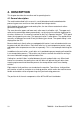

4.3 Process principle
In all processes the materials are fed through the nip from the infeed side to be joined
together by pressure and/or temperature.
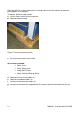
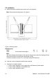
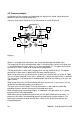
A process that makes maximum use of the machine is shown in figure 6.
Figure 6
Shown is an image roll to roll process with a heat activated top and bottom layer.
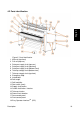
The image that has to be coated on both sides is unwound from a roll on an unwind shaft
(1) and fed between the main rollers (2) via the in-feed table (3). The upper unwind/wind-
up shaft (6) is set as a wind-up to roll up the finished product.
The top coating film is taken from a supply roll on the top unwind shaft (5). The bottom
coating film is taken from a supply roll on the lower unwind shaft (9).
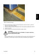
When using a pressure sensitive laminate, it often has a release liner (as shown in Figure
7) that has to be removed. It runs over a splitter bar (7) where the release liner is removed.
This release liner is rolled up onto a cardboard core placed on the wind-up shaft (4) in the
upper section.
When using a pressure sensitive laminate without a release liner, it must not run via the
splitter bar to avoid getting adhesive residue on it.
The main rollers can be heated. The heat activated film is fed under the splitter bar
providing maximum contact surface with the heated main rollers.
When encapsulating (hot sealing images), an additional set of pull rollers (8) is used to
prevent wrinkles after cooling down.
When continuously encapsulating (roll to roll) the chill idlers would warm up slowly. To
prevent the chill idlers from becoming too hot, the cooling fans can be turned on. The
cooling fans blow cool air onto the chill idlers, which in turn absorb the heat from the
encapsulated print.
1
2
3
6
5
9
11
8
20 7003338 - User Manual 65 Pro MD