
User manual

ZERO KIT
28
Instruction Manual.
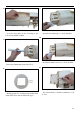
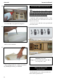
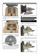
- Using a modeling knife, cut one length of sili-
con fuel line. Connect one end of the line to the
weighted fuel pick up and the other end to the ny-
lon pick up tube.
1.
3.
2.
4.
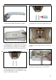
- Carefully bend the second nylon tube up at a 45º
angle. is tube is the vent tube.
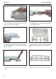
- Test t the stopper assembly into the tank. It
may be necessary to remove some of the ashing
around the tank opening using a modeling knife.
If ashing is present, make sure none falls into the
tank.
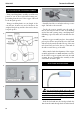
- With the stopper assembly in place, the weighted
pick-up should rest away from the rear of the tank
and move freely inside the tank. e top of the vent
tube should rest just below the top of the tank. It
should not touch the top of the tank.
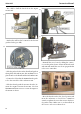
- When satised with the alignment of the stopper
assembly tighten the 3 x 20mm machine screw un-
til the rubber stopper expands and seals the tank
opening. Do not overtighten the assembly as this
could cause the tank to split.
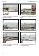
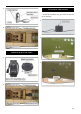
FUEL TANK INSTALLATION
1.
You should mark which tube is the vent
and which is the fuel pickup when you attach fuel
tubing to the tubes in the stopper. Once the tank
is installed inside the fuselage, it may be dicult
to determine which is which.
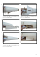
- Slide the fuel tank into the fuselage. Guide the
lines from the tank through the hole in the ewall.
INSTALLING THE STOPPER ASSEMBLY
- Using a modeling knife, carefully cut o the rear
portion of one of the 3 nylon tubes leaving 1/2”
protruding from the rear of the stopper. is will
be the fuel pick up tube.