Code : SEA 123K ASSEMBLY MANUAL Speciications: Wingspan--------------- 66.9 in (170.0 cm). Wing area--------------- 761.1 sq.ins (49.1 sq.dm). Weight------------------- 9.3 lbs (4.2 kg). Length------------------- 51.1 in (129.8 cm). Engine ------------------ 0.75 - 0.91 cu.in----2 stroke. ---------------------------- 0.91- 1.00 cu.in----4 stroke. Radio--------------------- 6 channels with 8 servos. Retracts landing gear (included).
Instruction Manual. ZERO KIT INTRODUCTION - Congratulations and thank you for purchasing the ZERO KIT. We are pleased to bring you this scale ZERO KIT with this kit you can achieve whatever level of detail you like. Just by following the instruction and inishing the plane in scale-looking trim scheme, beginning scale modelers will end up with a model that very much represents and full-size ZERO KIT.
ZERO KIT 4 Instruction Manual.
ZERO KIT 6 Instruction Manual.
ZERO KIT 8 Instruction Manual.
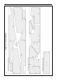
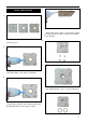
BUILD THE FUSELAGE 4. 1. - Put the F1 on F1A, F1B to paste them together and then ill Epoxy Glue around block include 3 layers irewall. - Firewall ( 3pcs). 5. 2. 6. - Fill White Glue to the surface of the F1B. 3. - Attach M4 blind nut ( 4pcs) to block of irewall . 7. - Put the F1A on F1B to paste them together and then ill White Glue on the surface of F1A.
Instruction Manual. ZERO KIT 8. 11. - Put former F2 on the right fuselage side S2’. - Attach the ring F34 ( 2 pcs) to block of irewall so that supporting keep fuel tank stopper. 12. 9. - Using the ruler to adjust perpendicular angle of - Arrange the let fuselage side S1 and the right fuformer F2 and the right fuselage side S2. selage side S2 as photo for diference inside surface and outside surface. 13. Please kindly see in the drawing sheet so that avoiding mistake at this step. 10.
17. 14. - Fill CA Glue to keep ixed F5A (2pcs) with the fuselage side S1, S2. - Fill CA Glue to keep ixed F3 with the fuselage side S1 and S2. 18. 15. - Fill CA Glue to keep ixed F5 with the fuselage side S1 and S2 and F24. - Fill CA Glue to keep ixed F4 with the fuselage side S1 and S2. 19. 16. - Fill CA Glue to keep ixed F24 with F1, F2, F3, F4, S1, S2. - Fill CA Glue to keep ixed F6 with the fuselage side S1 and S2, and then paste F6A on F6 at two side, and also install them to S1 and S2.
Instruction Manual. ZERO KIT 20. 23. - Fill Epoxy Glue around block include two layers 24. F6, F6A. Continue to former F7 to F11 as the instruction photos below.(photo 21-25) 21 . 25. 22. 26.
27. 30. 28. - Attach M3 blind nut ( 4pcs) to block of F12 , add thin White Glue. 31. - Using White Glue to paste former F12A, F12B and F12 ( 2pcs) and then ill Epoxy Glue around block. - Fill CA Glue to keep ixed block of F12 with the fuselage side S1 and S2. 29. 32. - Getting prepare for block include F14, F17, F18.
Instruction Manual. ZERO KIT 33. 36. - Install block at the end of fuselage by CA Glue. 34. - Install F13, F16, F19 together by CA Glue. 37. - Fill CA Glue to keep ixed block at the end of fuselage. - Fill CA Glue to keep the contact face with rudder at the end of fuselage. 38. 35. - Getting prepare for the contact face with rudder include F13, F16, F19.
39. 42. - Fill CA Glue to keep ixed SW1 at lelf side of fuselage, SW2 at right side of fuselage. - Install F2B at two side of fuselage by CA Glue. 43. 40. 41. - Getting prepare the mount of bottom hatch include F32 ( 2pcs). 44. - Install F33 at two side of fuselage by CA Glue. - Paste two F32 together by Epoxy Glue.
Instruction Manual. ZERO KIT 45. 48. - Fill CA Glue to keep ixed the bottom plate F25 at head of fuselage where for engine. - Attach M3 blind nut ( 2pcs) to block F32. 46. 49. - Upside down block F32 and add White Glue at M3 blind nut position. 47. - Attach the ring of wing nylon bolt F27 and F29 at two side of fuselage by Epoxy Glue. 50. - Fill CA Glue to keep ixed block F32 with fuselage ( Upside down fuselage so that installing F32 as photo).
51. 54. - Install F31 at two side of fuselage by Epoxy Glue. 52. - Paste F21A on F21 by Epoxy Glue. 55. - Install string of stick F20 at the top of fuselage by Epoxy Glue. 53. - Attach M3 blind nut to string of stick for antenna F21 as photo. 56. - Getting prepare string of stick for antenna include string of stick F21, the ring F21A and M3 blind nut. - Install string of stick F21 for antenna at the top of fuselage by CA Glue.
Instruction Manual. ZERO KIT 60. 57. - Install string of stick F21 at the bottom of fuselage by CA Glue. - Getting prepare for the latch of servo mount include FS2A (2pcs). 61. 58. - Getting prepare for mounting plate of battery include the ring F28, M4 blind nut. - Paste two latch FS2A together by Epoxy Glue. 62. 59. - Attach M4 blind nut to the latch. - Attach M4 blind nut to F28, and then paste them on F24 at holes position where put M4 inox bolt by Epoxy Glue.
63. 66. - Install the latch to let side of fuselage by Epoxy 67. Glue as photo. 64. - Paste F23 ( 2pcs) on the let side and right side of fuselage by CA Glue to support for putting the stabilizer. - Using Aluminium Square Fixed Tool to go through all formers at the square hole on each for- 68. mer. 65. - Install F15 to fuselage by CA Glue. - Install 4x4 stringers by Epoxy Glue.
Instruction Manual. ZERO KIT 69. 1. - Getting prepare for push rod include plastic tube 2. ( 3pcs) with Ø = 5mm. 70. - Install the plastic tube to go through all formers which have path of Fin and path of Elevator hole 3. on each former and ill White Glue to keep ixed. Please kindly see in the drawing sheet so that avoiding mistake at this step. SHEETING FOR RIBS OF FUSELAGE If the balsa sheet quite hard, we should use the wet towel so that making sot the balsa sheet.
4. 7. - Cover the sheet SH3 on ribs of fuselage at the both of side and ill CA Glue. - Cover the sheet SH6 on ribs of fuselage at the both of side and ill CA Glue. 5. 8. 6. 9. - Cover the sheet SH7 on ribs of fuselage at the both of side and ill CA Glue.
Instruction Manual. ZERO KIT 10. 13. - Cover the sheet SH4 on ribs of fuselage at the both of side and ill CA Glue. - Use sandpaper tube to sanding at the edge of SH5 as photo. 11. 14. 12. 15. - Cover the sheet SH5 on ribs of fuselage at the both of side and ill CA Glue. 22 - Cover the sheet SH8 on ribs of fuselage at the both of side and ill CA Glue.
16. 19. - Cover the sheet SH9 on ribs of fuselage at the both of side and ill CA Glue. - Attach the latch F30 (4pcs) to F2 by CA Glue. 20. 17. - Install F2A (8mm balsa sheet) to F2 by Ca Glue. - Removing Aluminium Square Fixed Tool. 21. 18. - Getting prepare for cowling mount include F2A (8mm balsa sheet) and the latch F30 ( 4pcs). - Use Cutter Knife to chamfer redundancy wood of F2A .
Instruction Manual. ZERO KIT 22. 25. - Use Sandpaper Bar to sanding block F2A , making for the edge to round shaping. 23. - Use Sandpaper Bar to sanding block F40, making to round shaping as F14. 26. - Install F40 (8mm balsa sheet) to the end of fuselage at two side of F17, also under F18 and behind F14 by CA Glue. - Getting prepare for bottom hatch include H1, H2, H3, H4, H5, H6, H7, H8 (2pcs), H9, H10 (cover sheet). 27. 24. - Use Cutter Knife to chamfer redundancy wood of F40.
28. 31. - Cover the sheet H10 on the frame by CA Glue. 29. - Fill White glue on the the tri-angle block as photo. 32. - Fitting the hatch into the fuselage, and then use - Attach two the tri-angle block to F1 inside the the Sandpaper Bar to sanding at the area contact fuselage. with the fuselage, on forward , also on behind so that setting up the hatch and the fuselage it togeth33. er. 30. - Install the wing paper tube into the fuselage.
Instruction Manual. ZERO KIT 34. INSTALLING THE FUSELAGE SERVOS Because the size of servos difer, you may need to adjust the size of the precut opening in the mount. he notch in the sides of the mount allow the servo lead to pass through. - Install the rubber grommets and brass collets onto the throttle servo. Test it the servo into the aileron servo mount. - Secure the servos with the screws provided with your radio system. - Use White Glue to keep ixed for wing tube. 35. 1. 2.
1. INSTALLING THE SWITCH - Install the switch into the precut hole in the side, in the fuselage. 1. 2. 2. SERVO GEAR INSTALLATION 1. 3. 2.
Instruction Manual. ZERO KIT INSTALLING THE STOPPER ASSEMBLY 4. - Using a modeling knife, carefully cut of the rear portion of one of the 3 nylon tubes leaving 1/2” protruding from the rear of the stopper. his will be the fuel pick up tube. - Carefully bend the second nylon tube up at a 45º angle. his tube is the vent tube. - Using a modeling knife, cut one length of silicon fuel line. Connect one end of the line to the weighted fuel pick up and the other end to the nylon pick up tube.
2. 5. Blow through one of the lines to ensure the fuel lines have not become kinked inside the fuel tank compartment. Air should low through easily. - Use plywood template to hold in place the fuel tank with C/A glue to secure the fuel tank inside the fuselage. MOUNTING THE ENGINE - 2 stroke 3. - Position the engine with the drive washer (150mm) forward of the irewall as shown. 1. 4. - Use a pin drill and 4mm drill bit to drill a small indentation in the mount for the engine mounting screw. 2.
Instruction Manual. ZERO KIT - Use a drill to drill the four holes in the engine mount rails. 5. 3. 6. - On the ire wall has the location for the throttle pusshrod tube (pre-drill). 4. - Reinstall the servo horn by sliding the connector over the pushrod wire. Center the throttle stick and trim and install the servo horn perpendicular to the servo center line. - Slide the pushrod tube in the iewall and guide it through the fuel tank mount. Use medium C/A to 7.
- Use a drill to drill the four holes in the engine mount rails. 8. 11. + 0.91 - 1.25 : 4 STROKE. - Position the engine with the drive washer (150mm) forward of the irewall as shown. - On the ire wall has the location for the throttle pusshrod tube (pre-drill). 9. 12. - Use a pin drill and 4mm drill bit to drill a small indentation in the mount for the engine mounting screw. 10. - Slide the pushrod tube in the irewall and guide it through the fuel tank mount.
Instruction Manual. ZERO KIT 13. 16. 14. COWLING - Slide the iberglass cowl over the engine and line up the back edge of the cowl with the marks you made on the fuselage then trim and cut as shown. 1. - Reinstall the servo horn by sliding the connector over the pushrod wire. Center the throttle stick and trim and install the servo horn perpendicular to the servo center line. 15. 2. - Move the throttle stick to the closed position and move the carburetor to closed. Use a 2.
3. 5. * Because of the size of the cowl, it may be necessary to use a needle valve extension for the high speed needle valve. Make this out of suicient length 1.5mm wire and install it into the end of the needle valve. Secure the wire in place by tightening the set screw in the side of the needle valve. 6. - While keeping the back edge of the cowl lush with the marks, align the front of the cowl with the crankshat of the engine.
Instruction Manual. ZERO KIT - Use mask the inside the canopy to protect it from over spray. INSTALLATION PILOT AND CANOPY 5. 1. - he Canopy. 2. - Paint follow the swell lines. 6. - Cut of redundan cy plastic around. 3. - Remove the mask - Locate items necessary to install pilot, cockpit panel, and canopy. 7. - Cover the rest of the clear area at the cells with masking tape, where no need painting. 4.
- A scale pilot is included with this ARF. he Pilot 11. included iting well to the coc pit. (or you can order others scale pilot iures made by SG Models. hey are available at SG Models distributors.) - If you are going to install a pilot iure, please use a sanding bar to sand the base of the iure so that it is lat. - Position the pilot iure on the canopy lor as show. Locate the oval shaped on the canopy lor and remove the covering.
Instruction Manual. ZERO KIT 14. 5. 6. INSTALL THE PLASTIC PARTS 1. BUILD THE WING 2. 1. 3. - Getting prepare the perpendicular frame include 2 pcs. 2. 4.
- Paste on them together. 6. 3. - Cut of redundancy of Aluminium Square Fixed Tool. - he Aluminium Square Fixed Tool be separated 2 parts. 7. 4. - Fixing the wing frame to Aluminium Square Fixed Tool. - Weld 2 parts the Aluminium Square Fixed Tool as perpendicular aluminium frame. 8. 5. - Fill White Glue at main edge of wing W20. - Build the ribs with the leading edge, main edge,trailing edge to frame of wing.
Instruction Manual. ZERO KIT 12. 9. - Paste stringer W21 on main edge of wing W20 by CA Glue. - Getting prepare mount of retract W46 (2pcs). 13. 10. - Install the mount of servo hatch ( 4pcs) W48, W49, W50, W51 by CA glue. - Use White glue to paste two W46 together. 14. 11. - Install W5A, W6A by CA Glue. 38 - Install mount of retract W46 to wing at W5A and W6A by CA Glue.
15. 18. - Paste W5B on W5 by CA Glue. - Fill CA glue on W46. 16. 19. - Fill White Glue at trailing edge, at bottom side of wing. - Paste W47 (2pcs) on W46 by CA Glue. 17. 20. - Install W18 and W18A for mount of retract by CA Glue. - Cover sheeting W45 by CA Glue.
Instruction Manual. ZERO KIT 24. 21. - Fill White glue at the ribs, at bottom side of wing. - Use CA glue inside to ix the sheet W45. 25. 22. - Cover sheeting W38 and then add more CA Glue. - Fill White glue at trailing edge leading by at top side of wing. 26 . 23. - Cover sheeting W45A by CA Glue at the tabs. 40 - Use CA glue inside to ix the sheet W38.
27. 30. - Add more CA glue to set of lock nut block. - Fill White glue at the face of leading edge. 28. 31. - Install lock nut block to inside wing at wing root by CA glue. - Paste 6mm balsa trading edge CA Glue. 29. 32. - Getting prepare the rectangle ring of nylon bolt W58 ( 4pcs) and the install nylon lock nut to the rectangle ring. - Fill White glue at the ribs, at the top side of wing.
Instruction Manual. ZERO KIT 33. 36. - Cover sheeting W37 and then add more CA glue. - Install wing paper tube to the wing, and add the ring W61, and measure excess part is15mm , and then ixed them by CA Glue. 34. 37. - Getting prepare the wing paper tube and the ring W60 to block up at a head of wing tube. - Cut of redundancy wing paper tube. 35. 38. - Paste the ring W60 to inside wing paper tube by CA Glue. 42 - Fixed by White glue at wing tube.
42. 39. - Paste the sheet W41 on the ribs and add more CA Glue. - Fill White glue on edge of W8, W9. 40. 43. - Paste the sheet W42 on the ribs and add more CA Glue. 41. - Fill White glue on edge of W11 and W12. 44. - Fill White glue on edge of W2, W3, W4, W5. - Paste the sheet W43 on the ribs and add more CA Glue.
Instruction Manual. ZERO KIT 48. 45. - Paste W33 on W3 by CA Glue. - Fill White glue on W45A, inside the lap. 49. 46. - Fill White Glue on edge of W2, W3, top side of wing. - Paste WA19 on W45A at trailing edge of lap, add more CA Glue. 50. 47. - Paste W34 on W7 by CA Glue. 44 - Paste the sheet W39 on the ribs and add more CA Glue.
51. 54. - Fill White glue on edge of W11, W12, top side of wing. - Add more CA glue at the tip to keep ixed. 55. 52. - Paste the sheet W43 on the ribs and add more CA Glue. - Install W31A at the tip of wing by CA glue. 56. 53. - Install W62 at the tip of wing by CA glue. - Install W15 at the tip of wing.
Instruction Manual. ZERO KIT 57. 60. - Use cutter knife to chamfer redundancy wood of W62. - Fill White Glue on face of W2. 61. 58. - Paste W1 on W2 as photo. - Use sandpaper bar to sanding for smoothing. 62. 59. - Use sandpaper bar to sanding at the W2. 46 - Paste W1 on W2 and add more CA glue to keep ixed.
63. 66. - Use sandpaper bar to sanding at the leading edge of wing. 64. - Use sandpaper bar to sanding at the leading edge of lap. 67. - Use the pen to take the mark for the hinge of lap. - Getting prepare the Flap include W35 and W36. 68. 65. - Paste W35 on W36 by CA glue - Use cutter knife to cut a line for the hinge on the wing at position of lap.
Instruction Manual. ZERO KIT 69. 72. - Use cutter knife to cut a line for the hinge on the lap. - Getting prepare the aileron as photo 72. 73. 70. - Install the ribs of aileron as photo 73. - Install the paper hinge ( 3pcs) for the lap. 74. 71. - Finished for the installing lap. 48 - Install triangle by CA glue.
75. 78. - Install the circle for supporting control horn by CA Glue. 76. - Use cutter knife to cut a line for the hinge on the wing at position of aileron. 79. - Use Sandpaper Bar to sanding at the leading edge of aileron. - Install the paper hinge ( 4pcs) for the aileron. 80. 77. - Use the pen to take the mark for the hinge of aileron. - Finished for the installing aileron.
Instruction Manual. ZERO KIT 81. HINGING THE AILERON Note : he control surfaces, including the ailerons, elevators, and rudder, are prehinged with hinges installed, but the hinges are not glued in place. It is imperative that you properly adhere the hinges in place per the steps that follow using a high-quality thin C/A glue. - Carefully remove the aileron from one of the wing panels. Note the position of the hinges. - Use Sandpaper to sanding the wing. 1. 82.
- Slide the wing panel on the aileron until there is 5. only a slight gap. he hinge is now centered on the wing panel and aileron. Remove the T-pins and snug the aileron against the wing panel. A gap of 1/64” or less should be maintained between the wing panel and aileron. 3. 6. - Delect the aileron and completely saturate each hinge with thin C/A glue. he ailerons front surface should lightly contact the wing during this procedure.
Instruction Manual. ZERO KIT 7. - Place epoxy into hole. his will harden the threads and prevent the crews from pulling loose. - hread a control horn end with aluminum washer, lock nut until the top edge of the end is 9mm from the vase of the horn as shown. 3. Note : Work the aileron up and down several times to “work in” the hinges and check for proper movement. INSTALL THE AILERONS CONTROL HORN - Locate the hardware necessary to install the control horns for the ailerons. 1. 4.
1. 4. 2. 5. 6. 3. 7.
Instruction Manual. ZERO KIT INSTALLING THE AILERON SERVOS AILERON PUSHROD HORN INSTALLATION - Install the elevator control horn using the same 1. method as same as the aileron control horns. 1. - Mark the control wire where it crosses the servo arm hole. 2. 2. 3. 3.
4. - Make a 90-degree bend at the mark and cut of the excess wire leaving 8mm past the bend. 5. 6. - Connect the linkage as shown and secure the control wire with a snap keeper. 7.
Instruction Manual. ZERO KIT - Cut the covering from the bottom of the wing for retracts landing gear installation. INSTALLING THE FLAP PUSHROD - Repeat the procedure for the aileron pushrod. 3. 1. - Glue hardwood mounting blocks into the wing as show with epoxy. 4. INSTALLING RETRACTABLE LANDING GEAR - Locate the items necessary to install the retractable landing gear as shown. 1. - Position the landing gear onto the landing gear rails. Mark the location of the holes for mouting the landing gear. 5.
8. 6. - Install the linkage into the connector on the end of the retract unit as shown. Mounting the landing gear to the rail with four M3x 2.5mm. 9. 7. 10. - Install a wheel and two wheel collars on the main landing gear. Secure the collars. - Install the wheel wells ater adjusting the retracts. Roughen the bottom side of the well and glue the wells using C/A glue as shown.
Instruction Manual. ZERO KIT 11. 13. 14. 12. SERVO GEAR 4.5KG (35X16X30MM) 1. 2. - Install the gear door to the retract strut. Apply a thin epoxy to the two gear door brackets to secure the gear door to the retract strut as shown.
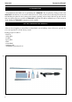
3. 7. INSTALLING RECEIVER 4. - Plug the ive servo leads and the switch lead into the receiver. Plug the battery pack ead into the switch also. - Wrap the receiver and battery pack in the protective foam rubber to protect them from vibration. - Route the antenna in the antenna tube inside the fuselage and secure it to the bot tom of fuselage using a plastic tape. 5. 1. 6.
Instruction Manual. ZERO KIT ATTACHMENT WING-FUSELAGE - Attach the aluminium tube into fuselage. 1. Insert two wing panels as pictures below. 2. 3. 60 4.
5. 6. 8.
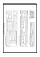
Instruction Manual. ZERO KIT BUILD THE HORIZONTAL STABILIZER 4. 1. - Hold the sheet down with weights while the glue dries. 5. - Getting prepare the horizontal stab as photo. 2. - Use sandpaper to sanding around the horizontal stab. - Install the frame of stabilizer by CA glue. BUILD THE ELEVATOR 3. 1. - Fill White Glue on the ribs and then cover the sheet ST1 ( 2pcs) for two side of horizontal stabilizer.
- Getting prepare a set of elevator include triangle 5. bar (1 pcs), the sheet ST16 and ST17, the ribs ST11, ST12, ST13, ST14, ST15, the ring ST19, and 8mm balsa block ( 1pcs) for supporting control horn. 2. - Use cutter knife to chamfer redundancy wood. 6. - Install the frame of elevator by Ca glue, add more white glue inside at all ribs. 3. - Use sandpaper bar to sanding surface of elevator. 7. - Add thin CA glue at all tab outside. 4. - Install the ring ST19 by CA glue at position of control horn.
Instruction Manual. ZERO KIT 11. 8. - Finished for the installing elevator. - Use the pen to take the mark for the hinge of elevator. 12. 9. - Use sandpaper to sanding the set of horizontal stab and elevator for smoothing the surface. - Use cutter knife to cut a line for the hinge on the horizontal stab and elevator. INSTALLING THE HORIZONTAL STABILIZER 10. - Using a ruler and a pen, locate the centerline of the horizontal stabilizer, at the trailing edge, and place a mark.
2. 4. - Put the stabilizer into place in the position of the fuselage. - Install the stabilizer onto the fuselage. Align the centerline drawn on the top and the rear of the stabilizer with the centre of the fuselage. When that is aligned, hold the stabilizer in that position using T-pins or masking tape. Align the horizontal stabilizer with the wing. When viewed from the rear, the horizontal stabilizer should be level with the wing.
Instruction Manual. ZERO KIT - Ater the epoxy has fully cured, remove the mask- 3. ing tape or T-pins used to hold the stabilizer in place. Carefully inspect the glue joints. Use more epoxy to ill in any gaps that may exist that were not illed previously and clean up the excess using a paper towel and rubbing alcohol. BUILD THE RUDDER AND FIN 1. - Add the white glue at all the ribs of rudder to corvering the sheet T1 ( 2pcs) for two side. 4. - Getting prepare set of rudder as photo. 2.
6. 9. - Add thin CA glue outside the sheet. 7. - Use sandpaper bar to sanding surface of rudder. 10. - Install 6mm balsa sheet (6pcs) T21 by CA glue as photo. 8. - Getting prepare balsa stick 3mm x 8mm ( 2pcs). 11. - Use cutter knife to chamfer redundancy wood. - Paste 3mmx8mm balsa stick under rudder by CA glue as photo.
Instruction Manual. ZERO KIT 12. 15. - Add thin CA glue at the tab outside the sheet. - Getting prepare set of in as photo. 16. 13. - Corvering the sheet T23 and T24 for two side by CA glue. - Install the in by CA glue as photo. 14. 17. - Add the white glue at all the ribs of in to corvering the sheet T35 ( 2pcs) for two side. 68 - Use the pen to take the mark for the hinge of in.
18. 21. - Use cutter knife to cut a line for the hinge on the rudder and in. - Use sandpaper to sanding the set of rudder and in for smoothing the surface. 19. SET UP THE FUSELAGE, THE HORIZONTAL STAB, THE RUDDER FOR THE KIT 1. - Install the paper hinge ( 2pcs) for rudder. 20. - Use sandpaper tube for sanding the area where install horizontal stabilizer. 2. - Finished for the installing rudder and in.
Instruction Manual. ZERO KIT - Install the horizontal stab to the fuselage. 6. 3. - Install both let wing, right wing and then adjust stabilizer and wing until they pararell absolately. - Using sandpaper tube to sanding rudder so that itting to the horizontal stab. INSTALLING VERTICAL STABILIZER 4. 1. - Using a modeling knife, remove the covering from over the precut hinge slot cut into the lower rear portion of the fuselage. - Install the rudder to the fuselage. 5. 2. 3.
- While holding the vertical stabilizer imly in 7. place, use a pen and draw a line on eachside of the vertical stabilizer where it meets the top of the fuselage. 4. - When you are sure that everything is aligned correctly, mix up a generous amount of Flash 30 Minute Epoxy. Apply a thin layer to the mounting slot and to bottom of the vertical stabilizer mounting area. Apply epoxy to the bottom and top edges of the iller block and to the lower hinge also. Set the stabilizer in place and realign.
Instruction Manual. ZERO KIT 10. 2. 11. 3. 12. MOUNTING THE TAIL WHEEL 1.
4. 4. HINGING THE RUDDER 5. - Glue the rudder hinges in place using the same techniques used to hinge the ailerons. 1. 6. 2. 3. 7.
Instruction Manual. ZERO KIT HINGING THE ELEVATORS 4. - Glue the elevator hinges in place using the same techniques used to hinge the ailerons. 1. 5. 2. 6. 3. INSTALL ELEVATOR CONTROL HORN - Install the elevator control horn using the same method as same as the aileron control horns.
1. 4. 2. ELEVATOR PUSHROD INSTALLATION - Install the elevator control horn using the same method as with the aileron control horns. 3. - Position the elevator control horn on the both side of elevator. 1. - hread one clevis and M2 lock nut on to each elevator control rod. hread the horns on until they are lush with the ends of the control rods. - Elevator and rudder pushrods assembly as pictures below. 2.
Instruction Manual. ZERO KIT 3. 7. 4. 8. 5. 9. 6. RUDDER PUSHROD INSTALLATION 1.
2. 7. 3. 8. 4. 5. 9. 6. 10.
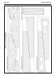
Instruction Manual. ZERO KIT 3. 11. - Fill white glue on surface MO2 ( include 2 layer). BUILD THE MOTOR MOUNT 4. 1. - Paste MO1 on MO2 ( include 2 layer). - Getting prepare set of motor mount as photo. 5. 2. - Add thin CA glue around block 3 layer. - Paste 2 pieces MO2 together by white glue.
6. 9. - Install block to the top of mount MO9. 7. - Add CA glue to paste them together. 10. - Install block to the right of mount MO8. - Getting prepare set of battery mount include MO3, MO4, MO5. 8. 11. - Install block to the let of mount MO7. - Paste them together by CA glue.
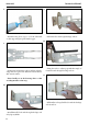
Instruction Manual. ZERO KIT 12. ELECTRIC POWER CONVERSION - Model size: .75-.90 size models - Motor: 50mm 310 rev per volt - Propeller: 14x10 ~ 15x10 - ESC: 60A - Lipo Batteries: 8 cell 3200mA - Attach the electric motor box to the irewall suitable with the cross lines drawn on the electric motor box and irewall. Using epoxy and balsa stick to secure the motor box to the irewall. Please see pictures below. - Getting prepare set of cowling mount include MO10 (2pcs), MO11(1pcs), MO12(7pcs).
6. 3. - Attach the speed control to the side of the motor box using two-sided tape and tie wraps. Connect the appropriate leads from the speed control to the motor. Make sure the leads will not interfere with the operation of the motor. - Attach the motor to the front of the electric motor box using four 4mm blind nut, four M4x15mm hex head bolts to secure the motor. Please see picture shown. 4. 5. - Locate the plywood battery tray to the fuselage.
Instruction Manual. ZERO KIT *If possible, ist attempt to balance the model by changing the position of the receiver battery and receiver. If you are unable to obtain good balance by doing so, then it will be necessary to add weight to the nose or tail to achieve the proper balance point. BALANCING - It is critical that your airplane be balanced correctly. Improper balance will cause your plane to lose control and crash.
If you have any queries, or are interested in our products, please feel free to contact us Factory : 12/101A - Hamlet 4 - Le Van Khuong Street - Dong hanh Ward Hoc Mon District - Ho Chi Minh City - Viet Nam. Oice : 62/8 Ngo Tat To Street - Ward 19 - Binh hanh District - Ho Chi Minh City - Viet Nam Phone : 848 - 86622289 or 848- 36018777 Website : www.SeagullModels.com Email : Sales@seagullmodels.com Facebook : www.facebook.com/SeaGullModels.