Code : SEA 114 ASSEMBLY MANUAL Speciications: Wingspan---------------80.5 in--------------(204.5cm) Wing area---------------1069.5--------------sq.ins (69 sq.dm) Weight-------------------11.9-13.2 lbs------(7.6kg) Length-------------------64.3 in -------------(163.
Instruction Manual. NEMESIS INTRODUCTION hank you for choosing the NEMESIS ARTF by SG MODELS . he NEMESIS was designed with the intermediate/advanced sport lyer in mind. It is a semi scale airplane which is easy to ly and quick to assemble. he airframe is conventionally built using balsa, plywood to make it stronger than the average ARTF, yet the design allows the aeroplane to be kept light. You will ind that most of the work has been done for you already.
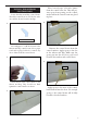
KIT CONTENTS SEA114 NEMESIS 1. Fuselage 2. Wing set (2) 3. Tail set (2) 4. Canopy 5. Cowling 6. Wing tube 7. Landing gear 8. Nose Landing gear 9. Fuel tank 10. Pushrod set 11. Ep Motor box 12. Pilot 13. Spinner � � � � � HINGING THE AILERON Note : he control surfaces, including the ailerons, elevators, and rudder, are prehinged with hinges installed, but the hinges are not glued in place.
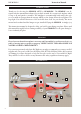
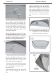
Instruction Manual. NEMESIS Ater both ailerons are securely hinged, irmly grasp the wing panel and aileron to make sure the hinges are securely glued and cannot be pulled out. Do this by carefully applying medium pressure, trying to separate the aileron from the wing panel. Use caution not to crush the wing structure. 3. 5. Delect the aileron and completely saturate each hinge with thin C/A glue. he ailerons front surface should lightly contact the wing during this procedure.
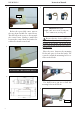
Place low-tack tape 1/32 inch (1mm) from the control horn slot. his will prevent epoxy from getting on the control surface when the control horns are glued in place. INSTALL THE AILERONS CONTROL HORN Locate the aileron and lap control horns. he taller control horn is used for the ailerons, and the shorter horn for the laps. 4. 1. Ailerons control horn Use sandpaper to scuf the bottom of the aileron and lap control horns.
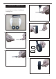
Instruction Manual. NEMESIS 6. 2. Epoxy Minimum servo spec. Torque : 6.0V: 192.4 oz-in (13.8 kg-cm) 7.4V: 350.0 oz-in (25.2 kg-cm) Before the epoxy fully cures, remove the tape from around the control horn. his will allow the epoxy to low around the control horn, creating a small ilet between the control horn and surface for a iished look and secure bond. Because the size of servos difer, you may need to adjust the size of the precut opening in the mount.
Apply 2-3 drops of thin C/A to each of the mounting holes. Allow the C/A to cure without using accelerator. 8. C/A glue 5. C/A glue Use dental loss or heatshrink tube to secure the connection so they cannot become unplugged. Remove the string from the wing at the servo location and use the tape to attach it to the servo extension lead. Pull the lead through the wing and remove the string. 9. 6. Secure the servo to the aileron hatch using Phillips screwdriver and the screws provided with the servo. 7.
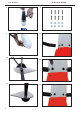
Instruction Manual. NEMESIS 11. AILERON PUSHROD INSTALLATION - Please study images below. 1. 12. 2. 75mm 3. M3 clevis M3 lock nut Set the aileron hatch in place and use a Phillips screw driver to install it with four wood screws. 13. 4. 3x10mm Hex Hex nut nut M3 clevis Fuel tubing 14.
INSTALLING LANDING GEAR 4. Locate items necessary to install Sprin Landing Gear. 1. 5. 2. 6. Collar. 3. M3x4mm. 7.
Instruction Manual. NEMESIS 8. 12. 9. 13. 10. 11. 10 14. 15.
THROTTLE SERVO ARM INSTALLATION INSTALLING THE FUSELAGE SERVOS . Because the size of servos difer, you may need to adjust the size of the precut . opening in the mount. he notch in the sides of the mount allow the servo lead to pass through. Install adjustable servo connector in the servo arm as same as picture below: 1. Install the rubber grommets and brass collets into all servos. Test it the servos into the fuselage servo mounts. Secure the servos with the screws provided with your radio system. 1.
Instruction Manual. NEMESIS INSTALLING THE SWITCH 5. Install the switch into the precut hole in the side, in the fuselage. 1. 3/32” Hole. 2. INSTALLING THE STOPPER ASSEMBLY Using a modeling knife, carefully cut of the rear portion of one of the 3 nylon tubes leaving 1/2” protruding from the rear of the stopper. his will be the fuel pick up tube. Using a modeling knife, cut one length of silicon fuel line.
2. FUEL TANK INSTALLATION 1. 3. Vent tube. Fuel pick up tube. You should mark which tube is the vent and which is the fuel pickup when you attach fuel tubing to the tubes in the stopper. Once the tank is installed inside the fuselage, it may be diicult to determine which is which. Fuel illtube. Slide the fuel tank into the fuselage. Guide the lines from the tank through the hole in the iewall. Carefully bend the second nylon tube up at a 45º angle. his tube is the vent tube.
Instruction Manual. NEMESIS 4. 8. Vent tube. Fuel pick up tube. Fuel ill tube. Connect the lines from the tank to the engine and muler. he vent line will connect to the muler and the line from the clunk tothe carburetor. 5. Blow through one of the lines to ensure the fuel lines have not become kinked inside the fuel tank compartment. Air should low through easily. MOUNTING THE ENGINE Please see below pictures. 6. 1. 7. 14 2.
3. 7. 5x90mm 4. 8. 5. 9. 6. 10.
Instruction Manual. NEMESIS 11. 15. 180mm Ignition Modude 12. 16. 13. 17. 14. 18.
19. 22. Reinstall the servo horn by sliding the connector over the pushrod wire. Center the throttle stick and trim and install the servo horn perpendicular to the servo center line. COWLING - Please see below pictures. 1. 20. 21. 2. Move the throttle stick to the closed position and move the carburetor to closed. Use a 2.5mm hex wrench to tighten the screw that secures the throttle pushrod wire. Make sure to use threadlock on the screw so it does not vibrate loose.
Instruction Manual. NEMESIS With the muler, needle valve, and spark/ glow plug removed from the engine, slide the cowl in place over the engine. Temporarily install the propeller and spinner in order to id the exact location of the cowl. When satisied with the cowl placement, secure the cowl to the fuselage using masking tape. 3. 7. 4. Install the muler and muler extension onto the engine and make the cutout in the cowl for muler clearance.
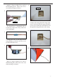
Because of the size of the cowl, it may be necessary to use a needle valve extension for the high speed needle valve. Make this out of suficient length 1.5mm wire and install it into the end of the needle valve. Secure the wire in place by tightening the set screw in the side of the needle valve. 12. 9. 13. 10. ELECTRIC POWER CONVERSION Locate the items neccessary to install the electric power conversion included with your model. 1. 11.
Instruction Manual. NEMESIS - Motor: 360 - 6000 Watts - Propeller: 24x10 ~ 25x12 - ESC: 160A - 200A - 12S Lipo 5. 2. 6. 3. Attach the electric motor box to the irewall centered with the cross lines drawn on the electric motor box and irewall. Using M6x25mm to secure the motor box to the irewall. Please see pictures below. 7. 4.
hen, use 8mm drill bit to enlarge the holes on the electric motor box. 8. 12. 6x35mm 8mm Attach the motor to the front of the electric motor box using four 4mm blind nut, four M6x35mm hex head bolts to secure the motor. Please see picture shown. 13. 9. Blind nut 10. 6mm. Attach the motor mount to the front of the electric motor box using four 4mm blind nut, four M6x25mm hex head bolts to secure the motor. Please see picture shown. 14. 6x25mm 11.
Instruction Manual. NEMESIS 18. 15. 180mm 16. Balsa stick 19. Epoxy Battery Attach the speed control to the side of the motor box using two-sided tape and tie wraps. Connect the appropriate leads from the speed control to the motor. Make sure the leads will not interfere with the operation of the motor. INSTALLING THE SPINNER - Install the spinner backplate, propeller and spinner cone. 1. 17. Speed control he propeller should not touch any part of the spinner cone.
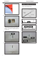
2. 3. Epoxy. HINGING THE ELEVATOR 4. Glue the elevator hinges in place using tthe same techniques as shown in images below. 1. 5. 2. INSTALL ELEVATOR CONTROL HORN 1. Fiberglass control horn.
Instruction Manual. NEMESIS 2. 6. 3. 7. 4. 8. Elevator iberglass control horn Epoxy Epoxy 5. HINGING THE RUDDER Epoxy 24 Glue the top three rudder hinges in place using the same techniques used to hinge the elevator. he lower hinge will be glued when the in/rudder assembly is attached to the fuselage.
1. INSTALL RUDDER CONTROL HORN Repeat steps to install the rudder control horn as same as steps done for elevator. 1. 2. Fiberglass control horn. 2. 3. Epoxy 3. 4.
Instruction Manual. NEMESIS 4. INSTALLING THE HORIZONTAL STABILIZER Using a ruler and a pen, locate the centerline of the horizontal stabilizer, at the trailing edge, and place a mark. Use a triangle and extend this mark, from back to front, across the top of the stabilizer. Also extend this mark down the back of the trailing edge of the stabilizer. Epoxy 1. 5. Draw center line Using a modeling knife, carefully remove the covering at mounting slot of horizontal stabilizer ( both side of fuselage).
3. 5. Epoxy When you are sure that everything is aligned correctly, mix up a generous amount of 30 Minute Epoxy. Apply a thin layer to the top and bottom of the stabilizer mounting area and to the stabilizer . mounting platform sides in the .fuselage. Slide the stabilizer in place and realign. Double check all of your measurements once more before the epoxy cures. Hold the stabilizer in place with T-pins or masking tape and remove any excess epoxy using a paper towel and rubbing alcohol.
Instruction Manual. NEMESIS INSTALLING VERTICAL STABILIZER 4. 1. Hinge Using a modeling knife, remove the covering from over the precut hinge slot cut into the lower rear portion of the fuselage. his slot accepts the lower rudder hinge. While holding the vertical stabilizer irmly in place, use a pen and draw a line on each side of the vertical stabilizer where it meets the top of the fuselage. 2. 5. 3. Epoxy Epoxy Slide the vertical stabilizer into the slot in the top of the fuselage.
9. 7. . When you are sure that everything is aligned correctly, mix up a generous amount of Flash 30 Minute Epoxy. Apply a thin layer to the mounting slot and to bottom of the vertical stabilizer mounting area. Apply epoxy to the bottom and top edges of the iller block and to the lower hinge also. Set the stabilizer in place and realign. Double check all of your measurements once more before the epoxy cures.
Instruction Manual. NEMESIS ELEVATOR PUSHROD INSTALLATION 5. Locate items necessary to install elevator pushrod. 1. RUDDER PUSHROD INSTALLATION Locate items necessary to install rudder pushrod. Elevator pushrods assembly as pictures below. 1. 2. Rudder pushrods assembly as pictures below. 3. 100mm 2. 750mm 4. 3.
4. 2. 5. 3. MOUNTING THE TAIL WHEEL 4. Locate items necessary to install tail wheel. 1. 5.
Instruction Manual. NEMESIS 6. 10. 7. 11. INSTALLATION PILOT AND CANOPY 8. Locate items necessary to install pilot, seats. 1. 9. 2.
3. 3. Epoxy 70mm 4. 4. Wing bolt C/A glue ATTACHMENT WING - FUSELAGE Attach the aluminium tube into fuselage. 5. 1. 6. 2.
NEMESIS 7. Instruction Manual. BALANCING An important part of preparing the aircrat for light is properly balancing the model. 1) Attach the wing panels to the fuselage. Make sure to connect the leads from the aileron to the appropriate leads from the receiver. Make sure the leads are not exposed outside the fuselage before tightening the wing bolts. Your model should be light-ready before balancing. 8.
1.
Instruction Manual. NEMESIS FLIGHT PREPARATION PREFLIGHT CHECK Check the operation and direction of the elevator, rudder, ailerons and throttle. 1) Completely charge your transmitter and receiver batteries before your irst day of lying. A) Plug in your radio system per the manufacturer’s instructions and turn everything on. B) Check the elevator irst. Pull back on the elevator stick. he elevator halves should move up.
If you have any queries, or are interested in our products, please feel free to contact us Factory : 12/101A - Hamlet 4 - Le Van Khuong Street - Dong hanh Ward Hoc Mon District - Ho Chi Minh City - Viet Nam. Oice : 62/8 Ngo Tat To Street - Ward 19 - Binh hanh District - Ho Chi Minh City - Viet Nam Phone : 848 - 86622289 or 848- 36018777 Website : www.SeagullModels.com Email : Sales@seagullmodels.com Facebook : www.facebook.com/SeaGullModels.