ASSEMBLY MANUAL ALMOST READY TO FLY “Graphics and specfications may change without notice”. Specifications Wing Span ------------------------------- 42.7 in --------------------- 108.5cm. 2 Wing Area ------------------------------- 376.7 sq in ------------ 24.3 sq dm. Weight --------------------------------- 2.4 - 2.9 Ibs------------ 1100 - 1300g. Length ------------------------------------ 38.8 in ----------------------- 98.6cm. Need to Complete Speed Control: 45A - 50A amp.
EDGE 540. Instruction Manual. INTRODUCTION. Thank you for choosing the EDGE 540 ARTF by SEAGULL EP. The EDGE 540 was designed with the intermediate/advanced sport flyer in mind. It is a semi scale airplane which is easy to fly and quick to assemble. The airframe is conventionally built using balsa, plywood to make it stronger than the average ARTF , yet the design allows the aeroplane to be kept light. You will find that most of the work has been done for you already.Flying the EDGE 540is simply a joy.
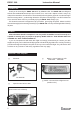
www.seagullmodels.com TOOLS & SUPPLIES NEEDED. Thick cyanoacrylate glue. 30 minute epoxy. 5 minute epoxy. Hand or electric drill. Assorted drill bits. Modelling knife. Straight edge ruler. 2mm ball driver. Phillips head screwdriver. 220 grit sandpaper. 90° square or builder’s triangle. Wire cutters. Masking tape & T-pins. Thread-lock. Paper towels. NOTE: To avoid scratching your new aeroplane we suggest that you cover your workbench with an old towel.
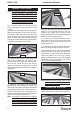
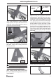
EDGE 540. Instruction Manual. HINGING THE AILERONS. Note: The control surfaces, including the ailerons, elevators, and rudder, are prehinged with hinges installed, but the hinges are not glued in place. It is imperative that you properly adhere the hinges in place per the steps that follow using a high-quality thin C/A glue. 1) Carefully remove the aileron from one of the wing panels. Note the position of the hinges.
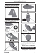
www.seagullmodels.com HINGING THE RUDDER. Glue the rudder hinges in place using the same tectniques used to hinge the ailerons. WHEEL AND WHEEL PANTS. C/A glue. Assemble and mounting the wheel pants as shown in the following pictures. C/A glue. C/A glue. A drop of C/A glue on the wheel collar screws will help keep them from coming lose during operation. C/A glue. Repeat the process for the other wheel. INSTALLING THE MAIN LANDING GEAR.
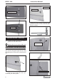
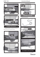
EDGE 540. Instruction Manual. Wing bottom. Aileron servo. Fuselage bottom. Attach the micro control connector to the servo arms. Be sure to use the lock tie but it could free rotation . 2 X 12mm. AILERON SERVOS - LINKAGES. 1) Install the rubber grommets and brass eyelets onto the aileron servo. Because the size of servos differ, you may need to adjust the size of the precut opening in the mount. The notch in the sides of the mount allow the servo lead to pass through.
www.seagullmodels.com Left side. Elevator servo. HORIZONTAL STABILIZER. Repeat the procedure for orther wing haft. 1) Using a ruler and a pen, locate the centerline of the horizontal stabilizer, at the trailing edge, and place a mark. Use a triangle and extend this mark, from back to front, across the top of the stabilizer. Also extend this mark down the back of the trailing edge of the stabilizer. Center line. FUSELAGE SERVO INSTALLATION.
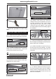
EDGE 540. Instruction Manual. Remove covering. Pen. Glued epoxy. 5) Remove the stabilizer. Using the lines you just drew as a guide, carefully remove the covering from between them using a modeling knife. Covered wood filler piece. Remove covering. VERTICAL STABILIZER INSTALLATION. When cutting through the covering to remove it, cut with only enough pressure to only cut through the covering itself. Cutting into the balsa structure may weaken it.
www.seagullmodels.com Horizontal Stabilizer. 3) While holding the vertical stabilizer firmly in place, use a pen and draw a line on each side of the vertical stabilizer where it meets the top of the fuselage. Pen. 4) Remove the stabilizer. Using a modeling knife, remove the covering from below the lines you drew. Remove covering. When cutting through the covering to remove it, cut with only enough pressure to only cut through the covering itself. Cutting into the balsa structure may weaken it.
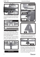
EDGE 540. Instruction Manual. C/A glue. Rudder servo. Elevator control horn. Rudder control horn. Elevator servo. MOUNTING THE TAIL SKID. See pictures below: Elevator control horn. C/A glue. PUSHROD INSTALLATION. Pushrod install as same as method of pushrod wing. See pictures below. C/A glue. Pushrod. ATTACHMENT WING-FUSELAGE. Attach the aluminium tube into fuselage.
www.seagullmodels.com Insert blind nut. Remove the covering. INSTALLING THE BATTERY-RECEIVER. See pictures below: C/A glue. Battery. Tie wrap. Receiver. Battery. Motor. Tie wrap. INSTALLING ELECTRIC MOTOR. There are 2 mouting box for your option.It is depended your motor size. 4.5 mm.
EDGE 540. Instruction Manual. Speed control. The propeller should not touch any part of the spinner cone. If it does, use a sharp modeling knife and carefully trim away the spinner cone where the propeller comes in contact with it. 5) Secure the cowl with the screw provide with hardware. COWLING INSTALLATION. 1) Using a pen to mark the points following the instruction below. PROPELLER INSTALLATION. The propeller should not touch any part of the fuselage side.
www.seagullmodels.com Wing brace. Insert two wing panels as pictures below. 7 cm. BALANCING. Wing bolt. 1) It is critical that your airplane be balanced correctly. Improper balance will cause your plane to lose control and crash. The center of gravity is locate 7cm back from the leading edge of the wing, measured at wing tip. 2) If the nose of the plane falls, the plane is nose heavy. To correct this first move the battery pack further back in the fuselage.
EDGE 540. 2) Turn on the radio system, and with the trim tabs on the transmitter in neutral, center the control surfaces by making adjustments to the clevises or adjustable servo connectors. The servo arms should be centered also. 3) When the elevator, rudder and aileron control surfaces are centered, use a ruler and check the amount of the control throw in each surface.