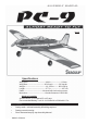
ASSEMBLY MANUAL MS: X8 Specifications Wing Span ------------------------------- 49.6 in ------------------ 126cm. Wing Area -----------------------------454.2 sq in ---------- 29.3 sq dm. Weight ----------------------------------- 1.9 -2.6 lbs ------- 850-1200 g. Length ------------------------------------ 37.7 in ------------------- 95.7cm. Radio ------------------------------- 4 channel with 4 sub-micro servos. Motor size ------------------------------- Himark Outrunner C3522-990.
PC9-EP. Instruction Manual. INTRODUCTION. Thank you for choosing the EP-PC9 ARTF by SEAGULL EP. The EP-PC9 was designed with the intermediate/advanced sport flyer in mind. It is a semi scale airplane which is easy to fly and quick to assemble. The airframe is conventionally built using balsa, plywood to make it stronger than the average ARTF , yet the design allows the aeroplane to be kept light. You will find that most of the work has been done for you already.Flying the EP-PC9 is simply a joy.
www.seagullmodels.com TOOLS & SUPPLIES NEEDED. ! ! ! ! ! ! ! ! ! ! ! ! ! ! ! Thick cyanoacrylate glue. 30 minute epoxy. 5 minute epoxy. Hand or electric drill. Assorted drill bits. Modelling knife. Straight edge ruler. 2mm ball driver. Phillips head screwdriver. 220 grit sandpaper. 90° square or builder’s triangle. Wire cutters. Masking tape & T-pins. Thread-lock. Paper towels. NOTE: To avoid scratching your new aeroplane we suggest that you cover your workbench with an old towel.
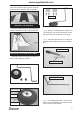
PC9-EP. Instruction Manual. HINGING THE AILERONS. Note: The control surfaces, including the ailerons, elevators, and rudder, are prehinged with hinges installed, but the hinges are not glued in place. It is imperative that you properly adhere the hinges in place per the steps that follow using a high-quality thin C/A glue.
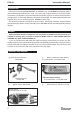
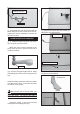
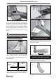
www.seagullmodels.com Glue the elevator hinges in place using the same tectniques used to hinge the ailerons. 3x10mm. HINGING THE RUDDER. Glue the rudder hinges in place using the same tectniques used to hinge the ailerons. ! 2) Using a modeling knife, remove the covering from over the two main gear mounting slots located in the bottom of the wing. ! 3) Insert the 90º bend of one main gear wire into the predrilled hole in one mounting slot. Wing bottom. INSTALLING THE MAIN GEAR WIRES.
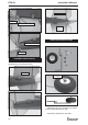
Landing gear wire. 2 x 12mm. ! 6) Reinstall the gear wire and install the straps using the four 2 x 12mm wood screws. Tighten the screws completely to secure the gear wire in place. ! 3)Secure the servos with the screws provided with your radio system. Wing bottom. AILERON SERVOS-LINKAGES. ! 1) Install the metal connector onto servo arm as same as picture below. Attach the micro control connector to the servo arms. Be sure to use the lock tie but it could free rotation . Aileron control horn slot.
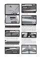
Left side. Rudder servo. Control horn. INSTALLING THE SWITCH. C/A glue. Install the switch into the precut hole in the side, in the fuselage. Switch. Pushrod wire. Control horn. Repeat the procedure for orther wing haft. FUSELAGE SERVO INSTALLATION. ! 1) Locate and cut out the covering film from the servo holes in both sides of fuselage. Right side. Remove covering. ! 2) Install the rubber grommets and brass collets onto the elevator servo. Test fit the servo into the elevator servo mount.
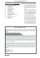
PC9-EP. Instruction Manual. ! 4) With the stabilizer held firmly in place, use a pen and draw lines onto the stabilizer where it and the fuselage sides meet. Do this on both the right and left sides and top and bottom of the stabilizer. Hinge. Pen. ! 1) Using a modeling knife, remove the covering from over the precut hinge slot cut into the lower rear portion of the fuselage. This slot accepts the lower rudder hinge. ! 5) Remove the stabilizer.
www.seagullmodels.com C/A glue. Pen. ! 4) Remove the stabilizer. Using a modeling knife, remove the covering from below the lines you drew. Also remove the covering from the bottom edge of the stabilizer and the bottom and top edges of the filler block. Leave the covering in place on the sides of the filler block. When cutting through the covering to remove it, cut with only enough pressure to only cut through the covering itself. Cutting into the balsa structure may weaken it. SERVO ARM INSTALLATION.
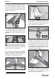
PC9-EP. Instruction Manual. Elevator servo. C/A glue. Elevator control horn. Rudder servo. NOSE GEAR INSTALLATION. Rudder control horn. C/A glue. PUSHROD INSTALLATION. Pushrod install as same as method of pushrod wing. See pictures below. Pushrod. C/a glue Adjust the nose gear steering arm until the arm is parallel with the fire wall. Install the pushrod wire as shown.
www.seagullmodels.com Blind nut. pushrod wire C/A glue. INSTALLING THE STEERING ARM SERVO. Attach the micro control connector to the servo arms. Be sure to use the lock tie but it could free rotation . Motor. Lock tie. ! 1) Install the rubber grommets and brass collets onto the stearing servo. Test fit the servo into the stearing servo mount. Because the size of servos differ, you may need to adjust the size of the precut opening in the mount.
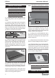
PC9-EP. Instruction Manual. Motor. 5.2cm 1cm 0.8cm ! 2) Slide the fiberglass cowl over the engine and line up the back edge of the cowl with the marks you made on the fuselage then trim and cut. The propeller should not touch any part of the spinner cone. If it does, use a sharp modeling knife and carefully trim away the spinner cone where the propeller comes in contact with it. ! 5) Secure the cowl with the screw provide with hardware. 2x8mm.
www.seagullmodels.com ATTACHMENT WING-FUSELAGE. Attach the aluminium tube into fuselage. !2) If the nose of the plane falls, the plane is nose heavy. To correct this first move the battery pack further back in the fuselage. If this is not possible or does not correct it, stick small amounts of lead weight on the fuselage sides under the horizontal stabilizer. If the tail of the plane falls, the plane is tail heavy.
PC9-EP. Instruction Manual. FLIGHT PREPARATION. PREFLIGHT CHECK. ! A) Check the operation and direction of the elevator, rudder, ailerons and throttle. !1) Completely charge your transmitter and receiver batteries before your first day of flying. ! B) Plug in your radio system per the manufacturer's instructions and turn everything on. ! C) Check the elevator first. Pull back on the elevator stick. The elevator halves should move up.