
Computer Hardware User Manual
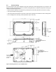
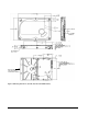
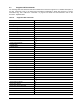
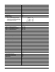
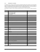
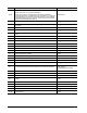
Table Of Contents
- 1.0 Introduction
- 2.0 Drive specifications
- 2.1 Specification summary tables
- 2.2 Formatted capacity
- 2.3 Default logical geometry
- 2.4 Recording and interface technology
- 2.5 Physical characteristics
- 2.6 Seek time
- 2.7 Start/stop times
- 2.8 Power specifications
- 2.9 Environmental specifications
- 2.10 Acoustics emissions
- 2.11 Electromagnetic immunity
- 2.12 Reliability
- 2.13 Agency certification
- 2.14 Environmental protection
- 2.15 Corrosive environment
- 3.0 Configuring and mounting the drive
- 4.0 Serial ATA (SATA) interface
- 5.0 Seagate Technology support services
- Index
Pipeline HD.2 Series SATA Product Manual, Rev. E 23
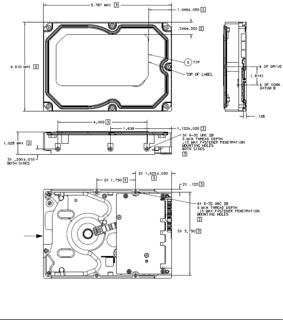
3.4 Drive mounting
You can mount the drive in any orientation using four screws in the side-mounting holes or four screws in the
bottom-mounting holes. Refer to Figure 3 for drive mounting dimensions. Follow these important mounting pre-
cautions when mounting the drive:
• Allow a minimum clearance of 0.030 in
ches (0.76mm) around the entire perimeter of the drive for cooling.
• Use only 6-32 UNC mounting screws.
• The screws should be inserted no more than 0.150 inches (3
.81mm) into the bottom or side mounting holes.
• Do not overtighten the mounting screws (maximum torque: 6 inch-lb).
Recommended
case temperature
measurement
location
Figure 3. Mounting dimensions (for 1000GB models)