Product Manual Savvio 15K.1 FC ® ST973451FC ST936751FC 100384763 Rev.
©2007, Seagate Technology LLC All rights reserved. Publication number: 100384763, Rev. B August 2007 Seagate, Seagate Technology and the Wave logo are registered trademarks of Seagate Technology LLC in the United States and/or other countries. LD25 Series, SeaTools and SeaTDD are either trademarks or registered trademarks of Seagate Technology LLC or one of its affiliated companies in the United States and/or other countries.
Contents 1.0 Scope . . . . . . . . . . . . . . . . . . . . . . . . . . . . . . . . . . . . . . . . . . . . . . . . . . . . . . . . . . . . . . . . . . . . . . . . 1 2.0 Applicable standards and reference documentation . . . . . . . . . . . . . . . . . . . . . . . . . . . . . . . . . 2.1 Standards . . . . . . . . . . . . . . . . . . . . . . . . . . . . . . . . . . . . . . . . . . . . . . . . . . . . . . . . . . . . . . 2.1.1 Electromagnetic compatibility. . . . . . . . . . . . . . . . . . . . . . . . . .
6.0 Physical/electrical specifications . . . . . . . . . . . . . . . . . . . . . . . . . . . . . . . . . . . . . . . . . . . . . . . . 6.1 AC power requirements . . . . . . . . . . . . . . . . . . . . . . . . . . . . . . . . . . . . . . . . . . . . . . . . . . . 6.2 DC power requirements . . . . . . . . . . . . . . . . . . . . . . . . . . . . . . . . . . . . . . . . . . . . . . . . . . . 6.2.1 Conducted noise immunity . . . . . . . . . . . . . . . . . . . . . . . . . . . . . . . . . . . . . . . . . 6.2.
9.5 9.6 10.0 FC-AL physical interface . . . . . . . . . . . . . . . . . . . . . . . . . . . . . . . . . . . . . . . . . . . . . . . . . . 9.5.1 Physical characteristics . . . . . . . . . . . . . . . . . . . . . . . . . . . . . . . . . . . . . . . . . . . 9.5.2 Connector requirements . . . . . . . . . . . . . . . . . . . . . . . . . . . . . . . . . . . . . . . . . . 9.5.3 Electrical description . . . . . . . . . . . . . . . . . . . . . . . . . . . . . . . . . . . . . . . . . . . . . 9.5.
iv Savvio 15K.1 FC Product Manual, Rev.
List of Figures Figure 1. Figure 2. Figure 3. Figure 4. Figure 5. Figure 6. Figure 7. Figure 8. Figure 9. Figure 10. Figure 11. Figure 12. Figure 13. Figure 14. Figure 15. Figure 16. Figure 17. Figure 18. Figure 19. Savvio 15K.1 family disc drive . . . . . . . . . . . . . . . . . . . . . . . . . . . . . . . . . . . . . . . . . . . . . . . . . 1 Typical ST973451FC drive +12V and +5V current profiles . . . . . . . . . . . . . . . . . . . . . . . . . .
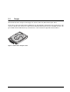
1.0 Scope This manual describes Seagate Technology® LLC, Savvio® 15K.1 FC (Fibre Channel) disc drives. Savvio drives support the Fibre Channel Arbitrated Loop and SCSI Fibre Channel Protocol specifications to the extent described in this manual. The Fibre Channel Interface Manual (part number 77767496) describes the general Fibre Channel Arbitrated Loop characteristics of this and other Seagate Fibre Channel drives. Figure 1. Savvio 15K.1 family disc drive Savvio 15K.1 FC Product Manual, Rev.
2 Savvio 15K.1 FC Product Manual, Rev.
2.0 Applicable standards and reference documentation The drive has been developed as a system peripheral to the highest standards of design and construction. The drive depends upon its host equipment to provide adequate power and environment in order to achieve optimum performance and compliance with applicable industry and governmental regulations. Special attention must be given in the areas of safety, power distribution, shielding, audible noise control, and temperature regulation.
2.1.2 Electromagnetic compliance Seagate uses an independent laboratory to confirm compliance with the directives/standards for CE Marking and C-Tick Marking. The drive was tested in a representative system for typical applications. The selected system represents the most popular characteristics for test platforms. The system configurations include: • Typical current use microprocessor • 3.
Seagate also has internal systems in place to ensure ongoing compliance with the RoHS Directive and all laws and regulations which restrict chemical content in electronic products. These systems include standard operating procedures that ensure that restricted substances are not utilized in our manufacturing operations, laboratory analytical validation testing, and an internal auditing process to ensure that all standard operating procedures are complied with. 2.3 Reference documents Savvio 15K.
6 Savvio 15K.1 FC Product Manual, Rev.
3.0 General description Savvio drives combine Tunneling Magnetoresistive (TMR) heads and a Fibre Channel interface to provide high performance, high capacity data storage for a variety of systems including engineering workstations, network servers, mainframes, and supercomputers. Savvio drives also support 4-Gbit Fibre Channel which can transfer data at up to 400 Mbytes per second and 800 Mbytes per second in dual-loop configurations.
3.1 Standard features Savvio drives have the following standard features: • Perpendicular recording technology • 4-Gbit Fibre Channel interface.
3.2 Media description The media used on the drive has an aluminum substrate coated with a thin film magnetic material, overcoated with a proprietary protective layer for improved durability and environmental protection. 3.3 Performance • Firmware-controlled multisegmented cache designed to dynamically adjust segments for enhanced system performance. • 400 Mbytes/sec maximum instantaneous data transfers per port • 15k RPM spindle; average latency = 2.
3.5.1 Programmable drive capacity Using the Mode Select command, the drive can change its capacity to something less than maximum. See the Mode Select (6) parameter list table in the Fibre Channel Interface Manual, part number 100293070. Refer to the Parameter list block descriptor number of blocks field. A value of zero in the number of blocks field indicates that the drive shall not change the capacity it is currently formatted to have.
4.0 Performance characteristics This section provides detailed information concerning performance-related characteristics and features of Savvio drives. 4.1 Internal drive characteristics Drive capacity Read/write data heads Tracks per surface (total) Tracks per inch Peak bits per inch Areal Density Internal data rate Sustained data transer rate Disc rotation speed Avg rotational latency 4.2 ST973451FC 73.4 4 42,554 150 861.81 130.58 957.51 to 1,282.08 57-89 15k 2.0 ST936751FC 36.2 2 42,554 150 861.
4.2.2 Format command execution time ST973451FC ST936751FC Maximum (with verify) 52 minutes 26 minutes Maximum (without verify) 35 minutes 18 minutes 4.2.
The START STOP UNIT command may be used to command the drive to stop the spindle. Stop time is 30 seconds (maximum) from removal of DC power. There is no power control switch on the drive. 4.4 Prefetch/multi-segmented cache control The drive provides a prefetch (read look-ahead) and multi-segmented cache control algorithms that in many cases can enhance system performance. Cache refers to the drive buffer storage space when it is used in cache operations.
If read caching is enabled (RCD=0), then data written to the medium is retained in the cache to be made available for future read cache hits. The same buffer space and segmentation is used as set up for read functions. The buffer segmentation scheme is set up or changed independently, having nothing to do with the state of RCD.
5.0 Reliability specifications The following reliability specifications assume correct host and drive operational interface, including all interface timings, power supply voltages, environmental requirements and drive mounting constraints.
5.1.2 Unrecoverable Errors An unrecoverable data error is defined as a failure of the drive to recover data from the media. These errors occur due to head/media or write problems. Unrecoverable data errors are only detected during read operations, but not caused by the read. If an unrecoverable data error is detected, a MEDIUM ERROR (03h) in the Sense Key will be reported. Multiple unrecoverable data errors resulting from the same cause are treated as 1 error. 5.1.
5.2.3 Hot plugging the drive Inserting and removing the drive on the FC-AL will interrupt loop operation. The interruption occurs when the receiver of the next device in the loop must synchronize to a different input signal. FC error detection mechanisms, character sync, running disparity, word sync, and CRC are able to detect any error. Recovery is initiated based on the type of error.
Performance impact S.M.A.R.T. attribute data is saved to the disc so that the events that caused a predictive failure can be recreated. The drive measures and saves parameters once every two hours subject to an idle period on the FC-AL bus. The process of measuring off-line attribute data and saving data to the disc is uninterruptable. The maximum on-line only processing delay is summarized below: Maximum processing delay S.M.A.R.T.
The thermal monitor system generates a warning code of 01-0B01 when the temperature exceeds the specified limit in compliance with the SCSI standard. The drive temperature is reported in the FRU code field of mode sense data. You can use this information to determine if the warning is due to the temperature exceeding the drive threatening temperature or the user-specified temperature.
5.2.6.2 Implementation This section provides all of the information necessary to implement the DST function on this drive. 5.2.6.2.1 State of the drive prior to testing The drive must be in a ready state before issuing the Send Diagnostic command. There are multiple reasons why a drive may not be ready, some of which are valid conditions, and not errors. For example, a drive may be in process of doing a format, or another DST.
5.2.6.2.4 Log page entries When the drive begins DST, it creates a new entry in the Self-test Results Log page. The new entry is created by inserting a new self-test parameter block at the beginning of the self-test results log parameter section of the log page. Existing data will be moved to make room for the new parameter block. The drive reports 20 parameter blocks in the log page. If there are more than 20 parameter blocks, the least recent parameter block will be deleted.
Product repair and return information Seagate customer service centers are the only facilities authorized to service Seagate drives. Seagate does not sanction any third-party repair facilities. Any unauthorized repair or tampering with the factory seal voids the warranty. 22 Savvio 15K.1 FC Product Manual, Rev.
6.0 Physical/electrical specifications This section provides information relating to the physical and electrical characteristics of the drive. 6.1 AC power requirements None. 6.2 DC power requirements The voltage and current requirements for a single drive are shown below. Values indicated apply at the drive connector.
Table 3: DC power requirements for ST936751FC Notes Voltage ST936751FC (1 Gbit) ST936751FC (2 Gbit) ST936751FC (4 Gbit) (Amps) (Amps) (Amps) (Amps) (Amps) (Amps) +5V +12V [2] +5V +12V [2] +5V +12V [2] Regulation [5] ±5% ±5% [2] ±5% ±5% [2] ±5% ±5% [2] Avg idle current DCX [1] [7] 0.71 0.15 0.72 0.15 0.79 0.15 Maximum starting current (peak DC) DC 3σ [3] 0.74 1.08 0.76 1.07 0.84 1.07 (peak AC) AC 3σ [3] 1.23 1.49 1.32 1.49 1.06 1.46 [1] [4] 0.42 0.01 0.
6.2.1 Conducted noise immunity Noise is specified as a periodic and random distribution of frequencies covering a band from DC to 10 MHz. Maximum allowed noise values given below are peak-to-peak measurements and apply at the drive power connector. +5V +12V 0 to 100 kHz 150mV 150mV 100 kHz to 10 MHz 100mV 100mV 6.2.2 Power sequencing The drive does not require power sequencing. The drive protects against inadvertent writing during power-up and down. 6.2.
Figure 3. Typical ST936751FC drive +12V and +5V current profiles 26 Savvio 15K.1 FC Product Manual, Rev.
6.3 Power dissipation ST973451FC Typical power dissipation under idle conditions in 1Gb operation is 5.58 watts (19.04 BTUs per hour). Typical power dissipation under idle conditions in 2Gb operation is 5.58 watts (19.04 BTUs per hour). Typical power dissipation under idle conditions in 4Gb operation is 5.88 watts (20.06 BTUs per hour). To obtain operating power for typical random read operations, refer to the following I/O rate curve (see Figure 4).
CURRENT/POWER vs THROUGHPUT (FC - 4GB) Random 8 Block Reads 1.400 14.00 5Vo lt A 12.00 1.000 10.00 0.800 8.00 0.600 6.00 0.400 4.00 0.200 2.00 0.000 Watts Power (watts) Amperes 12 Volt A 1.200 0.00 0.0 50.0 100.0 150.0 200.0 250.0 300.0 350.0 400.0 I/Os per Second Figure 6. ST973451FC DC current and power vs. input/output operations per second at 4 Gbit 28 Savvio 15K.1 FC Product Manual, Rev.
ST936751FC Typical power dissipation under idle conditions in 1Gb operation is 5.35 watts (18.26 BTUs per hour). Typical power dissipation under idle conditions in 2Gb operation is 5.4 watts (18.43 BTUs per hour). Typical power dissipation under idle conditions in 4Gb operation is 5.75 watts (19.62 BTUs per hour). To obtain operating power for typical random read operations, refer to the following I/O rate curve (see Figure 4).
FC CURRENT/POWER vs THROUGHPUT (FC - 4GB) Random 8 Block Reads 1.400 14.00 5Vo lt A 12.00 1.000 10.00 0.800 8.00 0.600 6.00 0.400 4.00 0.200 2.00 0.000 Watts Power (watts) Amperes 12 Volt A 1.200 0.00 0.0 50.0 100.0 150.0 200.0 250.0 300.0 350.0 400.0 450.0 I/Os per Second Figure 9. ST936751FC DC current and power vs. input/output operations per second at 4 Gbit 6.
b. Non-operating –40° to 158°F (–40° to 70°C) package ambient with a maximum gradient of 36°F (20°C) per hour. This specification assumes that the drive is packaged in the shipping container designed by Seagate for use with drive. HDA Temp. Check Point Figure 10. Locations of the HDA temperature check point 6.4.2 Relative humidity The values below assume that no condensation on the drive occurs. a. Operating 5% to 95% non-condensing relative humidity with a maximum gradient of 20% per hour. b.
abnormal levels may promote degraded operational performance during the abnormal shock period. Specified operational performance will continue when normal operating shock levels resume. Shock may be applied in the X, Y, or Z axis. Shock is not to be repeated more than two times per second. c. Non-operating The limits of non-operating shock shall apply to all conditions of handling and transportation. This includes both isolated drives and integrated drives.
Z X Y Z Y X Figure 11. Recommended mounting Savvio 15K.1 FC Product Manual, Rev.
6.4.4.2 Vibration a. Operating—normal The drive as installed for normal operation, shall comply with the complete specified performance while subjected to continuous vibration not exceeding 10-500 Hz @ 1.0 G (zero to peak) Vibration may be applied in the X, Y, or Z axis. Operating normal translational random flat profile 10 - 400 Hz 0.4 GRMS b.
6.4.7 Acoustics Sound power during idle mode shall be 3.1 bels typical when measured to ISO 7779 specification. There will not be any discrete tones more than 10 dB above the masking noise on typical drives when measured according to Seagate specification 30553-001. There will not be any tones more than 24 dB above the masking noise on any drive. 6.4.8 Electromagnetic susceptibility See Section 2.1.1.1. Savvio 15K.1 FC Product Manual, Rev.
6.5 Mechanical specifications Height: Width: Depth: Weight: 0.583 in 2.755 in 3.945 in 0.50 pounds 14.8 mm 69.98 mm 100.2 mm 0.227 kilograms 4.340 +/- .010 3.945 +/- .008 3.016 +/- .010 .276 .379 +/- .010 .118 +/- .008 .583 +/- .014 1.447 .158 .160 +/- .010 Measurements shown in inches 2.430 +/- .010 3.016 +/- .010 .379 +/- .010 2.755 +/- .008 Figure 12. Drive dimensions (inches) 36 Savvio 15K.1 FC Product Manual, Rev.
7.0 Defect and error management Seagate continues to use innovative technologies to manage defects and errors. These technologies are designed to increase data integrity, perform drive self-maintenance, and validate proper drive operation. SCSI defect and error management involves drive internal defect/error management and SAS system error considerations (errors in communications between the initiator and the drive).
The drive firmware error recovery algorithms consists of 11 levels for read recoveries and five levels for write. Each level may consist of multiple steps, where a step is defined as a recovery function involving a single reread or re-write attempt. The maximum level used by the drive in LBA recovery is determined by the read and write retry counts. Table 4 equates the read and write retry count with the maximum possible recovery time for read and write recovery of individual LBAs.
7.4 Background Media Scan Background Media Scan (BMS) is a self-initiated media scan. BMS is defined in the T10 document SPC-4 available from the T10 committee. BMS performs sequential reads across the entire pack of the media while the drive is idle. In RAID arrays, BMS allows hot spare drives to be scanned for defects prior to being put into service by the host system. On regular duty drives, if the host system makes use of the BMS Log Page, it can avoid placing data in suspect locations on the media.
7.7 Idle Read After Write Idle Read After Write (IRAW) utilizes idle time to verify the integrity of recently written data. During idle periods, no active system requests, the drive reads recently written data from the media and compares it to valid write command data resident in the drives data buffer. Any sectors that fail the comparison result in the invocation of a rewrite and auto-reallocation process. The process attempts to rewrite the data to the original location.
8.0 Installation Savvio disc drive installation is a plug-and-play process. There are no jumpers, switches, or terminators on the drive. Simply plug the drive into the host’s 40-pin Fibre Channel backpanel connector (FC-SCA)—no cables are required. See Section 9.5 for additional information about this connector. Use the FC-AL interface to select drive ID and all option configurations for devices on the loop.
Above unit Note. Air flows in the direction shown (back to front) or in reverse direction (front to back) Under unit Above unit Note. Air flows in the direction shown or in reverse direction (side to side) Under unit Figure 13. Air flow 8.3 Drive mounting Use M3 x .5 metric screws to mount the drive using either side, bottom, or end mounting holes. Select a screw length that results in a minimum thread engagement of 0.12 inches when using the side-mounting holes or a minimum thread engagement of 0.
9.0 Interface requirements This section partially describes the interface requirements as implemented on Savvio drives. Additional information is provided in the Fibre Channel Interface Manual (part number 100293070). 9.1 FC-AL features This section lists the Fibre Channel-specific features supported by Savvio drives. 9.1.1 Fibre Channel link service frames Table 5 lists the link services supported by Savvio drives.
9.1.2 Fibre Channel task management functions Table 6 lists the Fibre Channel SCSI Fibre Channel Protocol (FC SCSI FCP) task management functions supported. Table 6: Fibre Channel SCSI FCP task management functions Task name Supported Terminate task No Clear ACA No Target reset Yes Clear task set Yes Abort task set Yes 9.1.3 Fibre Channel task management responses Table 7 lists the FC SCSI FCP response codes returned for task management functions supported.
9.1.4 Fibre Channel port login Table 8 identifies the required content of the N_Port Login (PLOGI) payload from an initiator.
9.1.5 Fibre Channel port login accept Table 9 identifies the N_Port Login access payload values.
9.1.7 Fibre Channel Process Login Accept Table 11 lists Savvio process login accept payload data. Table 11: Process Login Accept (ACC) payload Bytes 0-15 02 10 00 14 16-31 00 00 00 12 9.1.8 08 00 21 00 00 00 00 00 00 00 00 00 Fibre Channel fabric login Table 12 lists the fabric login payload from the drive.
9.1.9 Fibre Channel fabric accept login Table 13 lists the required content of the Fabric Login Accept (ACC) payload from the fabric.
9.1.10 Fibre Channel Arbitrated Loop options Table 14 lists the FC-AL options supported by Savvio drives. Table 14: FC-AL options supported Option Supported OPEN Half Duplex Accepted from another device. OPEN Full Duplex Sent to open another device. Accepted from another device. Private Loop Yes Public Loop Yes Old Port State No Loop Position Yes Loop Position Report Yes 9.2 Dual port support Savvio drives have two independent FC-AL ports.
9.3 SCSI commands supported Table 15 lists the SCSI commands supported by Savvio drives.
Table 15: Supported commands (continued) Command code Supported [4] Command name Y Disconnect/reconnect control (page 02h) Y Format page (03h) Y Rigid disc drive geometry page (04h) Y Verify error recovery page (07h) Y Caching parameters page (08h) Y Control mode page (0Ah) Y Fibre Channel Interface Control page (19h) Y Power control page (1Ah) Y Information exceptions control page (1Ch) 1Bh Y Start unit/stop unit 1Ch Y Receive diagnostic results Y Supported diagnostics pages
Table 15: Supported commands (continued) Command code Supported [4] Command name 2Fh Y Verify Y Disable page out Y Byte check N Relative address 30h N Search data high 31h N Search data equal 32h N Search data low 33h N Set limits 34h N Prefetch 35h Y Synchronize cache 36h N Lock-unlock-cache 37h Y Read defect data 39h N Compare 3Ah N Copy and verify 3Bh Y Write buffer Y Write combined header and data mode (0) Y Write data mode (2) N Download microcode mod
Table 15: Supported commands (continued) Command code Supported [4] Command name N LBdata 42-4Bh N Not used 4Ch Y Log Select 4Dh Y Log Sense Y Support Log page (00h) Y Write Error Counter page (02h) Y Read Error Counter page (03h) N Read Reverse Error Counter page (04h) Y Verify Error Counter page (05h) Y Non-medium Error Counter page (06h) Y Temperature page (0Dh) N Application Client page (0Fh) Y Self Test Results page (10h) Y Cache Statistics Counter page (37h) Y Fact
Table 15: Supported commands (continued) Command code Supported [4] Command name 80h N XD write extended 81h N Rebuild 82h N Regenerate 83-8Fh N Not used A0h Y Report LUNS C0-DFh N Not used EO-FFh N Not used [1] [2] [3] [4] 54 Savvio drives can format to any multiple of four bytes per logical block in the range 512 to 528 bytes. Warning. Power loss during flash programming can result in firmware corruption. This usually makes the drive inoperable.
9.3.1 Inquiry data Table 16 lists the Inquiry command data that the drive should return to the initiator per the format given in the Fibre Channel Interface Manual.
9.4 Miscellaneous operating features and conditions Table 17 lists various features and conditions. A “Y” in the support column indicates the feature or condition is supported. An “N” in the support column indicates the feature or condition is not supported.
9.5 FC-AL physical interface Figure 14 shows the location of the J1 Fibre Channel single connection attachment (FC-SCA). Figure 16 provides the dimensions of the FC-SCA connector. Details of the physical, electrical, and logical characteristics are provided within this section. The operational aspects of Seagate’s Fibre Channel drives are provided in the Fibre Channel Interface Manual.. Figure 14. Physical interface 9.5.1 Physical characteristics This section defines physical interface connector. 9.5.
9.5.2 Connector requirements Table 19: Recommended mating SCA part numbers Part description Positions Part number Features AMP Vertical (SCA sequence) 40 787317-1 With polarization Berg 40 71781 With polarization Methode 40 512-220-91-101N With polarization Molex 40 717431040 With polarization The FC-AL SCA device connector is illustrated in Figure 16. 1.618 ± .003 in (41.1 ± 0.08 mm) Pin 20 Pin 40 Pin 1 Pin 21 .64 in (16.24 mm) 0.197 ± .003 in 2 places (5.00 ± .08 mm) 1.
9.5.4 Pin descriptions This section provides a pin-out of the FC-SCA and a description of the functions provided by the pins.
9.5.5 FC-AL transmitters and receivers A typical FC-AL differential copper transmitter and receiver pair is shown in Figure 17. The receiver is required to provide the AC coupling to eliminate ground shift noise. .01 TX Transmitter 100 100 Differential Transfer Medium RX 100 TY Receiver RY .01 Figure 17. FC-AL transmitters and receivers Savvio drives use 100 ohm termination which makes it compatible with backplanes designed for 1, 2, or 4 Gbit Fibre Channel transfer rates.
9.5.8 Active LED Out The Active LED Out signal is driven by the drive as indicated in Table 21.
Table 22: Motor start control signals Case Start_2 Start_1 Motor spin function 4 High High The drive will not spin up. 9.5.11 SEL_6 through SEL_0 ID lines The SEL_6 through SEL_0 ID lines determine drive address, and, optionally, for an Enclosure Services Interface. When the Parallel ESI line is high, the enclosure backpanel must provide address information on the SEL line. Refer to table 23 for a mapping of SEL to FC-AL physical addresses (AL_PA).
Table 23: Arbitrated loop physical address (AL_PA) values AL_PA (hex) SEL ID (hex) Setting (dec) AL_PA (hex) SEL ID (hex) Setting (dec) AL_PA (hex) SEL ID (hex) Setting (dec) EF 00 00 A3 2B 43 4D 56 86 E8 01 01 9F 2C 44 4C 57 87 E4 02 02 9E 2D 45 4B 58 88 E2 03 03 9D 2E 46 4A 59 89 E1 04 04 9B 2F 47 49 5A 90 E0 05 05 98 30 48 47 5B 91 DC 06 06 97 31 49 46 5C 92 DA 07 07 90 32 50 45 5D 93 D9 08 08 8F 33 51 43 5E 94 D6
9.5.12 Device control codes The drive inputs a Device Control Code on the DEV_CTRL_CODE lines at power up to determine the link rate on the Fibre Channel ports. Both ports run at the same rate. If the backpanel does not connect to these lines, the drive has 10K ohm pull up resistors that default the device control code to 7 (1.0625 GHz). Table lists the supported codes. Table 24: Device control code values 2 (pin 17) 1 (pin 18) 0 (pin 39) Definition 0 0 0 Reserved for power failure warning.
9.6.2 Differential PECL output The serial PECL output signal voltage characteristics are provided in Table 26. The outputs are not AC coupled in order to deliver maximum signal without rise and fall time degradation. You must AC couple the receiver to isolate potentially different DC characteristics of the outputs and the receiver. Table 26: Differential PECL output characteristics Description Parameter Notes Serial output voltage swing 600 < Vout < 1300 mV Centered at 1.
66 Savvio 15K.1 FC Product Manual, Rev.
10.0 Seagate Technology support services Internet For information regarding Seagate products and services, visit www.seagate.com. Worldwide support is available 24 hours daily by email for your questions. Presales Support: Presales@Seagate.com Technical Support: DiscSupport@Seagate.com Warranty Support: http://www.seagate.com/support/service/index.html mySeagate my.seagate.com is the industry's first Web portal designed specifically for OEMs and distributors.
Customer Service Operations Warranty Service Seagate offers worldwide customer support for Seagate products. Seagate distributors, OEMs and other direct customers should contact their Seagate Customer Service Operations (CSO) representative for warrantyrelated issues. Resellers or end users of drive products should contact their place of purchase or Seagate warranty service for assistance. Have your serial number and model or part number available.
Index Numerics 1 Gbit 60 12 volt pins 60 2 Gbit 60 3rd party reserve command 53 4 Gbit 60 5 volt pins 60 A Abort Sequence (ABTS) 43 abort task set function 44 AC coupling 60 AC power requirements 23 ACA active status 56 ACA active, faulted initiator status 56 Accept (ACC) 43 acoustics 35 active LED Out signal 61 Actual retry count bytes command 50 actuator assembly design 7 adaptive caching 56 Address Discovery (ADISC) 43 addresses 57 air cleanliness 34 air flow illustrated 42 Alternate credit model 45, 48
internal 11 data transfer rate 12 data valid eye 65 Date code page command 50 DC power 58 requirements 23 defect and error management 37 deferred error handling 56 description 7 DEV_CTRL_CODE 64 Device Behavior page command 50 device control code values 64 Device Identification page command 50 device selection IDs 41 devices 41 differential PECL input 65 Disable page out command 51, 52 disc rotation speed 11 Disconnect/reconnect control (page 02h) command 51 Download microcode and save modes (5) 52 Download
G hard assigned arbitrated loop physical address (AL_PA) 41 HDA 42 heads read/write data 11 host equipment 42 hot plugging the drive 17 humidity 31 humidity limits 30 Lock-unlock-cache command 52 Log select command 53 Log sense command 53 logic power 60 logical block address 13 logical block reallocation scheme 8 logical block size 8, 12 logical segments 13 Logout (LOGO) 43 loop 57, 61 disruption 17 initialization 41 loop position FC-AL options 49 loop position report FC-AL options 49 LS_RJT 45, 48 I M
command 50 monitoring state 17 motor start controls 61 mounting 42 orientations 41 mounting configuration dimensions 37 MTBF 9, 15, 16 N N_Port Login (PLOGI) 43 payload 45 payload values 46 NN 45, 48 Node Name 48 Node name 45 noise audible 3 noise immunity 25 non-operating 31, 32, 34 temperature 31 non-operating vibration 34 O office environment 34 ohm 60 old port state FC-AL options 49 OPEN Full Duplex FC-AL options 49 OPEN half duplex FC-AL options 49 Open sequences per exchange 45 operating 31, 34 opti
Read command 50 Read data mode (2) 52 Read defect data command 52 Read descriptor mode (3) 52 read error rates 15 Read extended command 51 Read Link Status (RLS) 43 Read long command 52 read/write data heads 11 Reassign blocks command 50 Receive buffer field size 45, 48 receive buffer field size 46 Receive diagnostic results command 51 receive eye diagram 65 receivers 60 recommended mounting 33 Recoverable Errors 15 recovered media data 15 reference documents 5 Regenerate command 54 Register FC-4 Types (RFT
Function not supported 05 44 Function reject 04 44 task set full status 56 technical support services 67 temperature 30 limits 30 non-operating 31 regulation 3 See also cooling terminate task function 44 termination 60 terminators 41 Test unit ready command 50 Third-party Process Logout (TRPLO) 43 tracks per inch 11 tracks per surface 11 Translate page command 51 transmit eye diagram 65 transmitters 60 transporting the drive 21 TTL input characteristics 64 XD write extended command 54 XID reassign 45 XP wr
Seagate Technology LLC 920 Disc Drive, Scotts Valley, California 95066-4544, USA Publication Number: 100384763, Rev.