Product Manual Savvio 10K.5 FC ® ST9900805FC ST9600205FC ST9450405FC ST9300605FC 100628563 Rev.
Revision history Revision Rev. A Rev. B Rev. C Rev. D Date 10/22/10 11/22/10 02/14/11 03/15/11 Sheets affected or comments Initial release. 41. 41. 27 & 36. © 2011 Seagate Technology LLC. All rights reserved. Publication number: 100628563, Rev. D, March 2011 Seagate, Seagate Technology and the Wave logo are registered trademarks of Seagate Technology LLC in the United States and/or other countries. Savvio 10K.
Contents 1.0 Seagate Technology support services . . . . . . . . . . . . . . . . . . . . . . . . . . . . . . . . . . . . . . . . . . . . . 1 2.0 Scope. . . . . . . . . . . . . . . . . . . . . . . . . . . . . . . . . . . . . . . . . . . . . . . . . . . . . . . . . . . . . . . . . . . . . . . . 2 3.0 Applicable standards and reference documentation . . . . . . . . . . . . . . . . . . . . . . . . . . . . . . . . . 3.1 Standards . . . . . . . . . . . . . . . . . . . . . . . . . . . . . . . . . . . . . . .
7.4 7.5 Power dissipation . . . . . . . . . . . . . . . . . . . . . . . . . . . . . . . . . . . . . . . . . . . . . . . . . . . . . . . . Environmental limits . . . . . . . . . . . . . . . . . . . . . . . . . . . . . . . . . . . . . . . . . . . . . . . . . . . . . . 7.5.1 Temperature . . . . . . . . . . . . . . . . . . . . . . . . . . . . . . . . . . . . . . . . . . . . . . . . . . . . 7.5.2 Relative humidity . . . . . . . . . . . . . . . . . . . . . . . . . . . . . . . . . . . . . . . . . . . . . . . . 7.
10.6 10.5.7 Fault LED Out . . . . . . . . . . . . . . . . . . . . . . . . . . . . . . . . . . . . . . . . . . . . . . . . . . 10.5.8 Active LED Out. . . . . . . . . . . . . . . . . . . . . . . . . . . . . . . . . . . . . . . . . . . . . . . . . . 10.5.9 Enable port bypass signals . . . . . . . . . . . . . . . . . . . . . . . . . . . . . . . . . . . . . . . . 10.5.10 Motor start controls . . . . . . . . . . . . . . . . . . . . . . . . . . . . . . . . . . . . . . . . . . . . . . 10.5.
iv Savvio 10K.5 FC Product Manual, Rev.
1.0 Seagate Technology support services SEAGATE ONLINE SUPPORT and SERVICES For information regarding products and services, visit http://www.seagate.com/www/en-us/about/contact_us/ Available services include: Presales & Technical support Global Support Services telephone numbers & business hours Authorized Service Centers For information regarding Warranty Support, visit http://www.seagate.
2.0 Scope This manual describes Seagate Technology® LLC, Savvio® 10K.5 FC (Fibre Channel) disk drives. Savvio 10K.5 FC drives support the Fibre Channel Arbitrated Loop and SCSI Fibre Channel Protocol specifications to the extent described in this manual. The Fibre Channel Interface Manual (part number 100293070) describes the general Fibre Channel Arbitrated Loop characteristics of this and other Seagate Fibre Channel drives. 2 Savvio 10K.5 FC Product Manual, Rev.
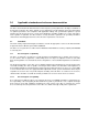
3.0 Applicable standards and reference documentation The drives documented in this manual have been developed as system peripherals to the highest standards of design and construction. The drives depend on host equipment to provide adequate power and environment for optimum performance and compliance with applicable industry and governmental regulations. Special attention must be given in the areas of safety, power distribution, shielding, audible noise control, and temperature regulation.
3.1.2 Electromagnetic compliance Seagate uses an independent laboratory to confirm compliance with the directives/standards for CE Marking and C-Tick Marking. The drive was tested in a representative system for typical applications. The selected system represents the most popular characteristics for test platforms.
3.2.1 China Restriction of Hazardous Substances (RoHS) Directive This product has an Environmental Protection Use Period (EPUP) of 20 years. The following table contains information mandated by China's "Marking Requirements for Control of Pollution Caused by Electronic Information Products" Standard. "O" indicates the hazardous and toxic substance content of the part (at the homogenous material level) is lower than the threshold defined by the China RoHS MCV Standard.
4.0 General description Savvio 10K.5 FC drives provide high performance, high capacity data storage for a variety of systems including engineering workstations, network servers, mainframes, and supercomputers. Savvio 10K.5 FC drives support 4-Gb Fibre Channel which can transfer data at up to 800MBs per second and 1600MBs per second in dualloop configurations. Savvio 10K.
4.1 Standard features Savvio 10K.
4.3 Performance • Programmable multi-segmentable cache buffer • 800MB/s maximum instantaneous data transfers per port • 10K RPM spindle. Average latency = 2.98ms • Command queuing of up to 128 commands • Background processing of queue • Supports start and stop commands (spindle stops spinning) • Adaptive seek velocity; improved seek performance 4.4 Reliability • Annualized Failure Rate (AFR) of 0.
4.6 Programmable drive capacity Using the Mode Select command, the drive can change its capacity to something less than maximum. See the Mode Select Parameter List table in the SCSI Commands Reference Manual. Refer to the Parameter list block descriptor number of blocks field. A value of zero in the number of blocks field indicates that the drive shall not change the capacity it is currently formatted to have.
5.0 Performance characteristics This section provides detailed information concerning performance-related characteristics and features of Savvio 10K.5 FC drives. 5.1 Internal drive characteristics Drive capacity* Read/write data heads Tracks per inch Peak bits per inch Areal density Internal data rate disk rotation speed Avg rotational latency ST9900805FC 900 6 300,000 1686 506 1.00 to 1.91 10K 3.0 ST9600205FC 600 4 300,000 1686 506 1.00 to 1.91 10K 3.
5.2.2 Format command execution time (minutes) ST9900805FC ST9600205FC ST9450405FC ST9300605FC Maximum (with verify) 234 156 117 78 Maximum (without verify) 116 75 58 36 5.2.3 General performance characteristics Sustainable disk transfer rate*: Data buffer to/from disc media (one 512-byte logical block)* Sustained transfer rate 1.00 to 1.
5.5 Cache operation Note. Refer to the Fibre Channel Interface Manual for more detail concerning the cache bits. Of the 64 Mbytes physical buffer space in the drive, approximately 30,000 kbytes are available as a data cache. The remaining buffer space is reserved for internal drive use. The drive keeps track of the logical block addresses of the data stored in each segment of the buffer.
5.5.1 Caching write data Write caching is a write operation by the drive that makes use of a drive buffer storage area where the data to be written to the medium is stored while the drive performs the Write command. If read caching is enabled (RCD=0), then data written to the medium is retained in the cache to be made available for future read cache hits. The same buffer space and segmentation is used as set up for read functions.
6.0 Reliability specifications The following reliability specifications assume correct host and drive operational interface, including all interface timings, power supply voltages, environmental requirements and drive mounting constraints. Seek error rate: Read Error Rates1 Recovered Data Unrecovered Data Miscorrected Data Interface error rate: Mean Time Between Failures (MTBF) Annualized Failure Rate (AFR): Preventive maintenance: 1.
6.1.3 Seek errors A seek error is defined as a failure of the drive to position the heads to the addressed track. After detecting an initial seek error, the drive automatically performs an error recovery process. If the error recovery process fails, a seek positioning error (Error code = 15h or 02h) will be reported with a Hardware error (04h) in the Sense Key. Recoverable seek errors are specified at Less than 10 errors in 108 seeks.
The Pass-through state is disabled while the drive performs self test of the FC interface. The control line for an external port bypass circuit remains in the Enable Bypass state while self test is running. If the bypass circuit is present, loop operation may continue. If the bypass circuit is not present, loop operation will be halted while the self test of the FC interface runs.
Reporting control Reporting is controlled by the MRIE bits in the Informational Exceptions Control mode page (1Ch). Subject to the reporting method. For example, if the MRIE is set to one, the firmware will issue to the host an 01-5D00 sense code. The FRU field contains the type of predictive failure that occurred. The error code is preserved through bus resets and power cycles. Determining rate S.M.A.R.T.
be used to set this trip point. The default value for this drive is 68°C, however, you can set it to any value in the range of 0 to 68°C. If you specify a temperature greater than 68°C in this field, the temperature is rounded down to 68°C. A sense code is sent to the host to indicate the rounding of the parameter field. Table 1: Temperature Log Page (0Dh) Parameter Code Description 0000h Primary Temperature 0001h Reference Temperature 6.2.
A Drive Not Ready condition is reported by the drive under the following conditions: • • • • Motor will not spin Motor will not lock to speed Servo will not lock on track Drive cannot read configuration tables from the disk In these conditions, the drive responds to a Test Unit Ready command with an 02/04/00 or 02/04/03 code. 6.2.6.2.
The drive will report the failure condition and LBA (if applicable) in the Self-test Results Log parameter. The Sense key, ASC, ASCQ, and FRU are used to report the failure condition. 6.2.6.2.5 Abort There are several ways to abort a diagnostic. You can use a SCSI Bus Reset or a Bus Device Reset message to abort the diagnostic. You can abort a DST executing in background mode by using the abort code in the DST Function Code field.
7.0 Physical/electrical specifications This section provides information relating to the physical and electrical characteristics of the drive. 7.1 PowerChoiceTM power management Drives using the load/unload architecture provide programmable power management to tailor systems for performance and greater energy efficiency. The table below lists the supported PowerChoice modes. The further you go down in the table, the more power savings you get.
7.1.1 PowerChoice reporting methods PowerChoiceTM provides these reporting methods for tracking purposes: Request Sense command reports • Current power condition • Method of entry Note. Processing the Request Sense command does not impact the drive’s power save state.
7.3 DC power requirements The voltage and current requirements for a single drive are shown below. Values indicated apply at the drive connector. Notes are shown following Table 5. Table 2: DC power requirements for ST9900805FC model 2Gb Notes Voltage 4Gb (Amps) (Amps) (Amps) (Amps) +5V +12V [2] +5V +12V [2] Regulation [6] ±5% ±5% [2] ±5% ±5% [2] Avg idle current DC [1] [8] 0.36 0.24 0.38 0.24 Advanced Idle Current Idle_A 3σ 0.37 0.24 0.39 0.25 Idle_B 3σ 0.25 0.21 0.
Table 3: DC power requirements for ST9600205FC model 2Gb Notes Voltage 4Gb (Amps) (Amps) (Amps) (Amps) +5V +12V [2] +5V +12V [2] Regulation [6] ±5% ±5% [2] ±5% ±5% [2] Avg idle current DC [1] [8] 0.37 0.18 0.39 0.18 Advanced Idle Current Idle_A 3σ 0.41 0.19 0.43 0.19 Idle_B 3σ 0.28 0.16 0.30 0.17 Idle_C 3σ 0.28 0.09 0.30 0.09 Standby 3σ 0.28 0.06 0.29 0.06 Maximum starting current (peak DC) DC 3σ [3] 0.64 0.90 0.66 0.89 (peak AC) AC 3σ [3] 0.97 1.
Table 4: DC power requirements for ST9450405FC model 2Gb Notes Voltage 4Gb (Amps) (Amps) (Amps) (Amps) +5V +12V [2] +5V +12V [2] Regulation [6] ±5% ±5% [2] ±5% ±5% [2] Avg idle current DC [1] [8] 0.37 0.18 0.38 0.18 Advanced Idle Current Idle_A 3σ 0.37 0.19 0.40 0.19 Idle_B 3σ 0.26 0.17 0.28 0.17 Idle_C 3σ 0.26 0.09 0.28 0.09 Standby 3σ 0.26 0.06 0.28 0.06 Maximum starting current (peak DC) DC 3σ [4] 0.64 0.89 0.65 0.89 (peak AC) AC 3σ [4] 0.96 1.
Table 5: DC power requirements for ST9300605FC model 2Gb Notes Voltage 4Gb (Amps) (Amps) (Amps) (Amps) +5V +12V [2] +5V +12V [2] Regulation [6] ±5% ±5% [2] ±5% ±5% [2] Avg idle current DC [1] [8] 0.36 0.15 0.38 0.15 Advanced Idle Current Idle_A 3σ 0.38 0.16 0.39 0.16 Idle_B 3σ 0.26 0.15 0.27 0.15 Idle_C 3σ 0.26 0.09 0.27 0.09 Standby 3σ 0.26 0.06 0.27 0.06 Maximum starting current (peak DC) DC 3σ [4] 0.61 0.89 0.63 0.89 (peak AC) AC 3σ [4] 0.95 1.
General DC power requirement notes. 1. Minimum current loading for each supply voltage is not less than 1.2% of the maximum operating current shown. 2. The +5V and +12V supplies should employ separate ground returns. 3. Where power is provided to multiple drives from a common supply, careful consideration for individual drive power requirements should be noted. Where multiple units are powered on simultaneously, the peak starting current must be available to each device. 4.
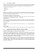
7.3.3 Current profiles The +12V and +5V current profiles for the all models are shown below. Note: All times and currents are typical. See Tables 2 through 5 for maximum current requirements. Figure 1. 28 Typical ST9900805FC drive, 4Gb, +5V and +12V current profiles Savvio 10K.5 FC Product Manual, Rev.
Figure 2. Typical ST9600205FC drive, 4Gb, +5V and +12V current profiles Savvio 10K.5 FC Product Manual, Rev.
Figure 3. 30 Typical ST9450405FC drive, 4Gb, +5V and +12V current profiles Savvio 10K.5 FC Product Manual, Rev.
Figure 4. Typical ST9300605FC drive, 4Gb, +5V and +12V current profiles Savvio 10K.5 FC Product Manual, Rev.
7.4 Power dissipation ST9900805FC Typical power dissipation under idle conditions in 4Gb operation is 4.77 Watts (16.26 BTUs per hour). To obtain operating power for typical random read operations, refer to the following I/O rate curve (see Figure 5). Locate the typical I/O rate for a drive in your system on the horizontal axis and read the corresponding +5 volt current, +12 volt current, and total watts on the vertical axis. To calculate BTUs per hour, multiply watts by 3.4123.
ST9600205FC Typical power dissipation under idle conditions in 4Gb operation is 4.13 watts (14.09 BTUs per hour). To obtain operating power for typical random read operations, refer to the following I/O rate curve (see Figure 5). Locate the typical I/O rate for a drive in your system on the horizontal axis and read the corresponding +5 volt current, +12 volt current, and total watts on the vertical axis. To calculate BTUs per hour, multiply watts by 3.4123. Figure 5. ST9600205FC DC current and power vs.
ST9450405FC Typical power dissipation under idle conditions in 4Gb operation is 4.07 watts (13.90 BTUs per hour). To obtain operating power for typical random read operations, refer to the following I/O rate curve (see Figure 5). Locate the typical I/O rate for a drive in your system on the horizontal axis and read the corresponding +5 volt current, +12 volt current, and total watts on the vertical axis. To calculate BTUs per hour, multiply watts by 3.4123. Figure 6.
ST9300605FC Typical power dissipation under idle conditions in 4Gb operation is 3.73 watts (12.72 BTUs per hour). To obtain operating power for typical random read operations, refer to the following I/O rate curve (see Figure 5). Locate the typical I/O rate for a drive in your system on the horizontal axis and read the corresponding +5 volt current, +12 volt current, and total watts on the vertical axis. To calculate BTUs per hour, multiply watts by 3.4123. Figure 7. ST9300605FC DC current and power vs.
7.5 Environmental limits Temperature and humidity values experienced by the drive must be such that condensation does not occur on any drive part. Altitude and atmospheric pressure specifications are referenced to a standard day at 58.7°F (14.8°C). Maximum wet bulb temperature is 82°F (28°C). Note. To maintain optimal performance drives should be run at nominal case temperatures. 7.5.1 Temperature a.
7.5.3 Effective altitude (sea level) a. Operating –1,000 to +10,000 feet (–304.8 to +3,048 meters) b. Non-operating –1,000 to +40,000 feet (–304.8 to +12,192 meters) 7.5.4 Shock and vibration Shock and vibration limits specified in this document are measured directly on the drive chassis. If the drive is installed in an enclosure to which the stated shock and/or vibration criteria is applied, resonances may occur internally to the enclosure resulting in drive movement in excess of the stated limits.
Figure 9. Recommended mounting Note. Image of the HDA may not represent actual product, for reference only 38 Savvio 10K.5 FC Product Manual, Rev.
7.5.4.2 Vibration a. Operating—normal The drive as installed for normal operation, shall comply with the complete specified performance while subjected to continuous vibration not exceeding 5-500 Hz @ 0.5 G (zero to peak) Vibration may be applied in the X, Y, or Z axis. Operating normal translational random flat profile 10 - 500 Hz (transactional random flat profile) 0.5 GRMS b.
7.5.7 Corrosive environment Seagate electronic drive components pass accelerated corrosion testing equivalent to 10 years exposure to light industrial environments containing sulfurous gases, chlorine and nitric oxide, classes G and H per ASTM B845. However, this accelerated testing cannot duplicate every potential application environment.
7.6 Mechanical specifications Refer to Figure 10 for detailed physical dimensions. See Section 9.4, “Drive mounting.” 300GB models 450GB models 600GB models 900GB models Weight: Note. .476 lb .485 lb .486 lb .462 lb .216 kg .220 kg .221 kg .210 kg These dimensions conform to the Small Form Factor Standard documented in SFF-8201 and SFF-8222, found at www.sffcommittee.org. in mm in mm in mm Figure 10. Mounting configuration dimensions Savvio 10K.5 FC Product Manual, Rev.
8.0 Defect and error management Seagate continues to use innovative technologies to manage defects and errors. These technologies are designed to increase data integrity, perform drive self-maintenance, and validate proper drive operation. SCSI defect and error management involves drive internal defect/error management and FC system error considerations (errors in communications between the initiator and the drive).
The drive firmware error recovery algorithms consist of 20 levels for read recoveries and five levels for write. Each level may consist of multiple steps, where a step is defined as a recovery function involving a single reread or re-write attempt. The maximum level used by the drive in LBA recovery is determined by the read and write retry counts. Table 6 equates the read and write retry count with the maximum possible recovery time for read and write recovery of individual LBAs.
8.4 Background Media Scan Background Media Scan (BMS) is a self-initiated media scan. BMS is defined in the T10 document SPC-4 available from the T10 committee. BMS performs sequential reads across the entire pack of the media while the drive is idle. In RAID arrays, BMS allows hot spare drives to be scanned for defects prior to being put into service by the host system. On regular duty drives, if the host system makes use of the BMS Log Page, it can avoid placing data in suspect locations on the media.
8.7 Idle Read After Write Idle Read After Write (IRAW) utilizes idle time to verify the integrity of recently written data. During idle periods, no active system requests, the drive reads recently written data from the media and compares it to valid write command data resident in the drives data buffer. Any sectors that fail the comparison result in the invocation of a rewrite and auto-reallocation process. The process attempts to rewrite the data to the original location.
8.8.3 Identifying a Protection Information drive The Standard Inquiry provides a bit to indicate if PI is support by the drive. Vital Product Descriptor (VPD) page 0x86 provides bits to indicate the PI Types supported and which PI fields the drive supports checking. Note. 46 For further details with respect to PI, please refer to SCSI Block Commands - 3 (SBC-3) Draft Standard documentation. Savvio 10K.5 FC Product Manual, Rev.
9.0 Installation Savvio 10K.5 FC disk drive installation is a plug-and-play process. There are no jumpers, switches, or terminators on the drive. Simply plug the drive into the host’s 40-pin Fibre Channel backpanel connector (FC-SCA) no cables are required. See Section 10.5 for additional information about this connector. Use the FC-AL interface to select drive ID and all option configurations for devices on the loop.
If forced air is necessary, possible air-flow patterns are shown in Figure 11. The air-flow patterns are created by fans either forcing or drawing air as shown in the illustrations. Conduction, convection, or other forced air-flow patterns are acceptable as long as the temperature measurement guidelines of Section 7.5.1 are met. Above unit Note. Air flows in the direction shown (back to front) or in reverse direction (front to back) Under unit Above unit Note.
9.5 Grounding Signal ground (PCBA) and HDA ground are connected together in the drive and cannot be separated by the user. The equipment in which the drive is mounted is connected directly to the HDA and PCBA with no electrically isolating shock mounts. If it is desired for the system chassis to not be connected to the HDA/PCBA ground, the systems integrator or user must provide a nonconductive (electrically isolating) method of mounting the drive in the host equipment.
10.0 Interface requirements This section partially describes the interface requirements as implemented on Savvio 10K.5 FC drives. Additional information is provided in the Fibre Channel Interface Manual (part number 100293070). 10.1 FC-AL features This section lists the Fibre Channel-specific features supported by Savvio 10K.5 FC drives. 10.1.1 Fibre Channel link service frames Table 7 lists the link services supported by Savvio 10K.5 FC drives.
10.1.2 Fibre Channel task management functions Table 8 lists the Fibre Channel SCSI Fibre Channel Protocol (FC SCSI FCP) task management functions supported. Table 8: Fibre Channel SCSI FCP task management functions Task name Supported Terminate task No Clear ACA Yes Target reset Yes Clear task set Yes Abort task set Yes 10.1.3 Fibre Channel task management responses Table 9 lists the FC SCSI FCP response codes returned for task management functions supported.
10.1.4 Fibre Channel port login Table 10 identifies the required content of the N_Port Login (PLOGI) payload from an initiator.
10.1.5 Fibre Channel port login accept Table 11 identifies the N_Port Login access payload values.
10.1.7 Fibre Channel Process Login Accept Table 13 lists Savvio 10K.5 FC process login accept payload data. Table 13: Process Login Accept (ACC) payload Bytes 0-15 02 10 00 14 16-31 00 00 00 12 10.1.8 08 00 21 00 00 00 00 00 00 00 00 00 Fibre Channel fabric login Table 14 lists the fabric login payload from the drive.
10.1.9 Fibre Channel fabric accept login Table 15 lists the required content of the Fabric Login Accept (ACC) payload from the fabric.
10.1.10 Fibre Channel Arbitrated Loop options Table 16 lists the FC-AL options supported by Savvio 10K.5 FC drives. Table 16: FC-AL options supported Option Supported OPEN Half Duplex Accepted from another device. OPEN Full Duplex Sent to open another device. Accepted from another device. Private Loop Yes Public Loop Yes Old Port State No Loop Position Yes Loop Position Report Yes 10.2 Dual port support Savvio 10K.5 FC drives have two independent FC-AL ports.
10.3 SCSI commands supported Table 17 lists the SCSI commands supported by Savvio 10K.5 FC drives.
Table 17: Supported commands (continued) Command code Supported [4] Command name Y Verify error recovery page (07h) Y Caching parameters page (08h) Y Control mode page (0Ah) Y Fibre Channel Interface Control page (19h) Y Power control page (1Ah) Y Information exceptions control page (1Ch) Y Background Scan mode subpage (01h) 1Bh Y Start unit/stop unit 1Ch Y Receive diagnostic results Y Supported diagnostics pages Y Translate page Y Enclosure services page Y Send diagnostics p
Table 17: Supported commands (continued) Command code Supported [4] Command name 32h N Search data low 33h N Set limits 34h N Prefetch 35h Y Synchronize cache 36h N Lock-unlock-cache 37h Y Read defect data 39h N Compare 3Ah N Copy and verify 3Bh Y Write buffer Y Write combined header and data mode (0) Y Write data mode (2) N Download microcode mode (4) Y Download microcode and save modes (5) N Download microcode with offsets mode (6) Y Download microcode with offse
Table 17: Supported commands (continued) Command code Supported [4] Command name Y Temperature page (0Dh) N Application Client page (0Fh) Y Self Test Results page (10h) Y Background Medium Scan page (15h) Y Cache Statistics Counter page (37h) Y Factory Log page (3Eh) 4E-4Fh N Not used 50h N XD write 51h N XP write 52h N XD read 53-54h N Not used 55h Y Mode Select (10) [3] 56h Y Reserved (10) Y 3rd party reserve N Extent reservation 57h Y Released (10) 58-59h N
10.3.1 Inquiry data Table 18 lists the Inquiry command data that the drive should return to the initiator per the format given in the Fibre Channel Interface Manual. Table 18: Savvio 10K.
On drives requiring unique saved values, the required unique saved values are stored into the saved values storage location on the media prior to shipping the drive. Some drives may have unique firmware with unique default values also. On standard OEM drives, the saved values are taken from the default values list and stored into the saved values storage location on the media prior to shipping. 3. Current values Current values are volatile values being used by the drive to control its operation.
Table 19: Mode Sense data saved, default and changeable values for ST9900805FC drives MODE DATA HEADER: 00 e2 00 10 01 00 00 10 BLOCK DESCRIPTOR: 00 00 00 00 68 cb 9e 30 00 00 00 00 00 00 02 00 MODE PAGES: DEF CHG 81 0a c0 14 ff 00 00 00 05 00 ff ff 81 0a ff ff 00 00 00 00 ff 00 ff ff DEF CHG 82 0e 80 80 00 00 00 00 00 00 01 3a 00 00 00 00 82 0e ff ff 00 00 00 00 00 00 ff ff 00 00 00 00 DEF CHG 83 16 bb d0 00 00 00 00 03 80 04 c4 02 00 00 01 00 a0 00 18 40 00 00 00 83 16 00 00 00 00 00 00 00 00 00 00
Table 20: Mode Sense data saved, default and changeable values for ST9600205FC drives MODE DATA HEADER: 00 e2 00 10 01 00 00 10 BLOCK DESCRIPTOR: 00 00 00 00 45 dd 2f b0 00 00 00 00 00 00 02 00 MODE PAGES: DEF CHG 81 0a c0 14 ff 00 00 00 05 00 ff ff 81 0a ff ff 00 00 00 00 ff 00 ff ff DEF CHG 82 0e 80 80 00 00 00 00 00 00 01 3a 00 00 00 00 82 0e ff ff 00 00 00 00 00 00 ff ff 00 00 00 00 DEF CHG 83 16 bb d0 00 00 00 00 03 80 04 c4 02 00 00 01 00 9a 00 18 40 00 00 00 83 16 00 00 00 00 00 00 00 00 00 00
Table 21: Mode Sense data default and changeable values for ST9450405FC drives MODE DATA HEADER: 00 e2 00 10 01 00 00 10 BLOCK DESCRIPTOR: 00 00 00 00 34 65 f8 70 00 00 00 00 00 00 02 00 MODE PAGES: DEF CHG 81 0a c0 14 ff 00 00 00 05 00 ff ff 81 0a ff ff 00 00 00 00 ff 00 ff ff DEF CHG 82 0e 80 80 00 00 00 00 00 00 01 3a 00 00 00 00 82 0e ff ff 00 00 00 00 00 00 ff ff 00 00 00 00 DEF CHG 83 16 bb d0 00 00 00 00 03 80 04 c4 02 00 00 01 00 9a 00 18 40 00 00 00 83 16 00 00 00 00 00 00 00 00 00 00 00 00
Table 22: Mode Sense data default and changeable values for ST9300605FC drives MODE DATA HEADER: 00 e2 00 10 01 00 00 10 BLOCK DESCRIPTOR: 00 00 00 00 22 ec b2 5c 00 00 00 00 00 00 02 00 MODE PAGES: DEF CHG 81 0a c0 14 ff 00 00 00 05 00 ff ff 81 0a ff ff 00 00 00 00 ff 00 ff ff DEF CHG 82 0e 80 80 00 00 00 00 00 00 01 3a 00 00 00 00 82 0e ff ff 00 00 00 00 00 00 ff ff 00 00 00 00 DEF CHG 83 16 bb d0 00 00 00 00 03 80 04 c4 02 00 00 01 00 9a 00 18 40 00 00 00 83 16 00 00 00 00 00 00 00 00 00 00 00 00
10.4 Miscellaneous operating features and conditions Table 23 lists various features and conditions. A “Y” in the support column indicates the feature or condition is supported. An “N” in the support column indicates the feature or condition is not supported.
10.5 FC-AL physical interface Figure 12 shows the location of the J1 Fibre Channel single connection attachment (FC-SCA). Figure 14 provides the dimensions of the FC-SCA connector. Details of the physical, electrical, and logical characteristics are provided within this section. The operational aspects of Seagate’s Fibre Channel drives are provided in the Fibre Channel Interface Manual. Figure 12. Physical interface Note. Image of the HDA may not represent actual product, for reference only. 10.5.
Figure 13. Port bypass circuit physical interconnect 10.5.2 Connector requirements The FC-AL SCA device connector is illustrated in Figure 14. Figure 14. FC-AL SCA device connector dimensions 10.5.3 Electrical description Fibre Channel drives use the FC-SCA connector for: • • • • • DC power FC-AL interface Drive select (device identification) Option selection Enclosure Services interface This 40-pin connector is designed to plug directly into a backpanel. External cables are not required. 10.5.
Table 25: FC-SCA pin descriptions Pin Signal name Signal type Pin Signal name 1* -EN bypass port A Low Voltage TTL output 21 12 Volts charge 2* 12 Volts 22 Ground 3* 12 Volts 23 Ground 4* 12 Volts 24* +Port A_in 5* -Parallel ESI 25* -Port A_in 6* Ground[1] 26 Ground 7* Active LED out 27* +Port B_in 8* Reserved 28* -Port B_in 9* [2] TTL input 29 Ground [2] Start_1 Open collector out Signal type FC Diff. input pair FC Diff.
10.5.6 Power Power is supplied through the FC-SCA with support for +5 volts and +12 volts. All of the voltage pins in the drive connector are the same length. Four 12 volt pins provide +12 volt power to the drive. The current return for the +12 volt power supply is through the common ground pins. The supply current and return current must be distributed as evenly as possible among the pins. The maximum current typically occurs while the drive motor is starting.
10.5.8 Active LED Out The Active LED Out signal is driven by the drive as indicated in Table 26.
10.5.11 SEL_6 through SEL_0 ID lines The SEL_6 through SEL_0 ID lines determine drive address, and, optionally, for an Enclosure Services Interface. When the Parallel ESI line is high, the enclosure backpanel must provide address information on the SEL line. Refer to table 28 for a mapping of SEL to FC-AL physical addresses (AL_PA). You can think of the SEL lines as the equivalent of a backpanel logic plug. The drives does not provide pull up resistors on these lines.
Table 28: Arbitrated loop physical address (AL_PA) values AL_PA (hex) SEL ID (hex) Setting (dec) AL_PA (hex) SEL ID (hex) Setting (dec) AL_PA (hex) SEL ID (hex) Setting (dec) EF E8 E4 E2 00 01 02 03 00 01 02 03 A3 9F 9E 9D 2B 2C 2D 2E 43 44 45 46 4D 4C 4B 4A 56 57 58 59 86 87 88 89 E1 E0 DC DA D9 D6 D5 D4 D3 D2 04 05 06 07 08 09 0A 0B 0C 0D 04 05 06 07 08 09 10 11 12 13 9B 98 97 90 8F 88 84 82 81 80 2F 30 31 32 33 34 35 36 37 38 47 48 49 50 51 52 53 54 55 56 49 47 46 45 43 3c 3A 39
10.5.12 Device control codes The drive inputs a Device Control Code on the DEV_CTRL_CODE lines at power up to determine the link rate on the Fibre Channel ports. Both ports run at the same rate. If the backpanel does not connect to these lines, the drive has 10K ohm pull up resistors that default the device control code to 7 (1.0625 GHz). Table lists the supported codes. Table 29: Device control code values 2 (pin 17) 1 (pin 18) 0 (pin 39) Definition 0 0 0 Reserved for power failure warning.
10.6.2 LED driver signals Fault and Active LED signals are located in the FC-SCA connector (J1). See Table 31 for the output characteristics of the LED drive signals. Table 31: LED drive signal State Current drive available LED off, high 0 < IOH < 100µA LED on, low IOL < -30 mA 10.6.3 Output voltage 0 < VOL < 0.8V FC Differential output The serial output signal voltage characteristics are provided in Table 32.
Figure 17 provides the data valid eye diagram for typical and minimum requirements to recover data at the specified interface error rate. The inputs are AC coupled on the drive. Vin (mv) 941 ps 659 ps Typical 376 ps Minimum Figure 17. Receive eye diagram Table 34: Eye diagram data values Link rate 1 GHz 2 GHz 4 GHz Bit time 941 ps 470 ps 235 ps XMIT eye 725 ps min. 315 ps min. 1581/1132 Typical 659 ps 305 ps 145 ps Minimum 395 ps 226 ps 113 ps RCV eye 1. 2. Short Ideal load.
78 Savvio 10K.5 FC Product Manual, Rev.
Index Numerics 12 volt pins 71 3rd party reserve command 60 5 volt pins 71 A Abort Sequence (ABTS) 50 abort task set function 51 AC coupling 70 AC power requirements 22 ACA active status 67 ACA active, faulted initiator status 67 Accept (ACC) 50 acoustics 39 active LED Out signal 72 Actual retry count bytes command 57 actuator assembly design 6 adaptive caching 67 Address Discovery (ADISC) 50 addresses 68 AFR 14 air cleanliness 39 air flow 48 illustrated 48 Alternate credit model 52, 55 altitude 37 ambient
D DAR 44 data block size modifing the 8 data buffer to/from disc media 11 data heads read/write 10 data rate internal 10 data transfer rate 11 data valid eye 77 Date code page command 57 DC power 69 requirements 23 defect and error management 42 defects 42 Deferred Auto-Reallocation 44 deferred error handling 67 description 6 DEV_CTRL_CODE 75 Device Behavior page command 57 device control code values 75 Device Identification page command 57 device selection IDs 47 devices 47 dimensions 41 Disable page out c
corruption 60 Firmware download option command 59 Firmware numbers page command 57 flawed sector reallocation 7 FLOGI received on Port A 54 received on Port B 54 Force unit access command 58 form factor 7 format 47 Format command execution time 11 Format page (03h) command 57 Format unit command 57 FS 52, 53, 55 function complete, code 00 51 not supported, code 05 51 reject, code 04 51 G commands supported 57 description 68 error rate 14 errors 15 illustrated 68 physical 68 requirements 50 intermediate/co
Media Pre-Scan 44 miscellaneous feature support Adaptive caching 67 Asynchronous event notification 67 Automatic contingent allegiance 67 Deferred error handling 67 FC-AL selective reset 67 Parameter rounding 67 Queue tagging 67 Reporting actual retry count 67 Segmented caching 67 SMP = 1 in Mode Select command 67 Synchronized (locked) spindle operation 67 Zero latency read 67 miscellaneous status support ACA active 67 ACA active, faulted initiator 67 Busy 67 Check condition 67 Condition met/good 67 Good 67
accept 53 Port Name 55 Port name (initiator’s) 52 power 71 dissipation 32 requirements, AC 22 requirements, DC 23 sequencing 27 Power Condition mode page 21 Power control page (1Ah) command 58 power distribution 3 power failure warning 75 power management 21 PowerChoice 21 PowerChoice reports 22 Prefetch command 59 prefetch/multi-segmented cache control 11 preventive maintenance 14 private loop FC-AL options 56 Proc Assc 52 Process Accept (ACC) 54 Process Login (PRLI) 50, 53 Process Login Accept (ACC) paylo
Self-Monitoring Analysis and Reporting Technology 8, 16 Send diagnostics page command 58 Sequential delivery 52, 55 Service Options 55 Service options 52 Set limits command 59 shielding 3 shipping 20 shipping container 36 shock 37 and vibration 37 shock mount 49 signal characteristics 75 LED driver 76 single-unit shipping pack kit 9 SMART 8, 16 SMP = 1 in Mode Select command 67 SO 52, 55 spindle brake 7 Stacked connection req.
zone bit recording (ZBR) 7 Savvio 10K.5 FC Product Manual, Rev.
86 Savvio 10K.5 FC Product Manual, Rev.
Seagate Technology LLC 920 Disc Drive, Scotts Valley, California 95066-4544, USA Publication Number: 100628563, Rev.