Product Manual Savvio SAS ST973401SS ST936701SS 100350598 Rev.
Copyright © 2007 Seagate Technology LLC. All rights reserved. Printed in U.S.A. Publication number: 100350598, Rev. D, August 2007 Seagate, Seagate Technology and the Wave logo are registered trademarks of Seagate Technology LLC in the United States and/or other countries. Savvio, SeaTools and SeaTDD are either trademarks or registered trademarks of Seagate Technology LLC or one of its affiliated companies in the United States and/or other countries.
Contents 1.0 Scope . . . . . . . . . . . . . . . . . . . . . . . . . . . . . . . . . . . . . . . . . . . . . . . . . . . . . . . . . . . . . . . . . . . . . . . . 1 2.0 Applicable standards and reference documentation . . . . . . . . . . . . . . . . . . . . . . . . . . . . . . . . . 2.1 Standards . . . . . . . . . . . . . . . . . . . . . . . . . . . . . . . . . . . . . . . . . . . . . . . . . . . . . . . . . . . . . . 2.1.1 Electromagnetic compatibility. . . . . . . . . . . . . . . . . . . . . . . . . .
6.4.1 Temperature . . . . . . . . . . . . . . . . . . . . . . . . . . . . . . . . . . . . . . . . . . . . . . . . . . . . 6.4.2 Relative humidity . . . . . . . . . . . . . . . . . . . . . . . . . . . . . . . . . . . . . . . . . . . . . . . . 6.4.3 Effective altitude (sea level) . . . . . . . . . . . . . . . . . . . . . . . . . . . . . . . . . . . . . . . . 6.4.4 Shock and vibration . . . . . . . . . . . . . . . . . . . . . . . . . . . . . . . . . . . . . . . . . . . . . . 6.4.5 Air cleanliness . . . . . . .
List of Figures Figure 1. Figure 2. Figure 3. Figure 4. Figure 5. Figure 6. Figure 7. Figure 8. Figure 9. Figure 10. Figure 11. Figure 12. Figure 13. Figure 14. Figure 15. Figure 16. Figure 17. Figure 18. Figure 19. Figure 20. Figure 21. Figure 22. Figure 23. Figure 24. Typical ST973401SS drive +12V current profile. . . . . . . . . . . . . . . . . . . . . . . . . . . . . . . . . . . Typical ST973401SS drive +5V current profile. . . . . . . . . . . . . . . . . . . . . . . . . . . . . . . . . . . .
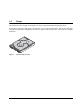
1.0 Scope This manual describes Seagate Technology® LLC, Savvio® SAS (Serial Attached SCSI) disc drives. Savvio drives support the SAS Protocol specifications to the extent described in this manual. The SAS Interface Manual (part number 100293071) describes the general SAS characteristics of this and other Seagate SAS drives. Figure 1. Savvio family disc drive Savvio SAS Product Manual, Rev.
2 Savvio SAS Product Manual, Rev.
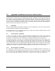
2.0 Applicable standards and reference documentation The drive has been developed as a system peripheral to the highest standards of design and construction. The drive depends on its host equipment to provide adequate power and environment for optimum performance and compliance with applicable industry and governmental regulations. Special attention must be given in the areas of safety, power distribution, shielding, audible noise control, and temperature regulation.
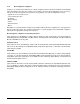
2.1.2 Electromagnetic compliance Seagate uses an independent laboratory to confirm compliance with the directives/standards for CE Marking and C-Tick Marking. The drive was tested in a representative system for typical applications. The selected system represents the most popular characteristics for test platforms. The system configurations include: • • • • • • • Typical current use microprocessor 3.
2.2 Reference documents Savvio SAS Installation Guide Seagate part number: 100350599 SAS Interface Manual Seagate part number: 100293071 ANSI SAS Documents SFF-82232.5” Drive Form Factor with Serial Connector SFF-8460HSS Backplane Design Guidelines SFF-8470Multi Lane Copper Connector SFF-8482SAS Plug Connector ANSI INCITS.
6 Savvio SAS Product Manual, Rev.
3.0 General description Savvio drives combine Tunneling Magnetoresistive (TMR) heads and a Serial Attached SCSI (SAS) interface to provide high performance, high capacity data storage for a variety of systems including engineering workstations, network servers, mainframes, and supercomputers. The Serial Attached SCSI interface is designed to meet next-generation computing demands for performance, scalability, flexibility and high-density storage requirements.
3.1 Standard features Savvio drives have the following standard features: • • • • • • • • • • • • • • • • • • • • • • • • • • 1.5 / 3 Gbit Serial Attached SCSI (SAS) interface Integrated dual port SAS controller supporting the SCSI protocol Support for SAS expanders and fanout adapters Firmware downloadable using the SAS interface 64 - deep task set (queue) Supports up to 32 initiators Jumperless configuration.
3.4 • • • • • Reliability Mean time between failures (MTBF) of 1,400,000 hours LSI circuitry Balanced low mass rotary voice coil actuator Incorporates industry-standard Self-Monitoring Analysis and Reporting Technology (S.M.A.R.T.) 5-year warranty 3.5 Formatted capacities Standard OEM models are formatted to 512 bytes per block. The block size is selectable at format time and must be a multiple of 4 bytes.
3.8 Factory-installed options You may order the following items which are incorporated at the manufacturing facility during production or packaged before shipping. Some of the options available are (not an exhaustive list of possible options): • Other capacities can be ordered depending on sparing scheme and sector size requested. • Single-unit shipping pack. The drive is normally shipped in bulk packaging to provide maximum protection against transit damage.
4.0 Performance characteristics This section provides detailed information concerning performance-related characteristics and features of Savvio drives. 4.1 Internal drive characteristics Drive capacity Read/write data heads Bytes per track Bytes per surface Tracks per surface (total) Tracks per inch Peak bits per inch Internal data rate Disc rotation speed Avg rotational latency 4.2 ST973401SS 73.4 4 360,000 18,387 51,052 105 660 506-753 10k 3.0 ST936701SS 36.
4.2.2 Format command execution time for 512-byte sectors (minutes) ST973401SS ST936701SS Maximum (with verify) 52 26 Maximum (without verify) 26 13 4.2.
4.3 Start/stop time The drive accepts the commands listed in the SAS Interface Manual less than 3 seconds after DC power has been applied. If the drive receives a NOTIFY (ENABLE SPINUP) primitive through either port and has not received a START STOP UNIT command with the START bit equal to 0, the drive becomes ready for normal operations within 20 seconds (excluding the error recovery procedure).
2. When a requested logical block is reached that is not in any cache segment, the drive fetches it and any remaining requested logical block addresses from the disc and puts them in a segment of the cache. The drive transfers the remaining requested logical blocks from the cache to the host in accordance with the Mode Select Disconnect/Reconnect parameters, page 02h. 3. If the prefetch feature is enabled, refer to section 4.5.2 for operation from this point.
4.5.2 Prefetch operation If the Prefetch feature is enabled, data in contiguous logical blocks on the disc immediately beyond that which was requested by a Read command are retrieved and stored in the buffer for immediate transfer from the buffer to the host on subsequent Read commands that request those logical blocks (this is true even if cache operation is disabled).
16 Savvio SAS Product Manual, Rev.
5.0 Reliability specifications The following reliability specifications assume correct host and drive operational interface, including all interface timings, power supply voltages, environmental requirements and drive mounting constraints. Seek error rate: Read Error Rates1 Recovered Data Unrecovered Data Miscorrected Data Interface error rate: MTBF: Service Life Preventive maintenance: 1.
5.1.3 Seek errors A seek error is defined as a failure of the drive to position the heads to the addressed track. After detecting an initial seek error, the drive automatically performs an error recovery process. If the error recovery process fails, a seek positioning error (Error code = 15h or 02h) will be reported with a Hardware error (04h) in the Sense Key. Recoverable seek errors are specified at Less than 10 errors in 108 seeks.
5.2.3 Hot plugging the drive When a disc is powered on by switching the power or hot plugged, the drive runs a self test before attempting to communicate on its’ interfaces. When the self test completes successfully, the drive initiates a Link Reset starting with OOB. An attached device should respond to the link reset. If the link reset attempt fails, or any time the drive looses sync, the drive initiated link reset. The drive will initiate link reset once per second but alternates between port A and B.
Reporting control Reporting is controlled by the MRIE bits in the Informational Exceptions Control mode page (1Ch). Subject to the reporting method, the firmware will issue to the host an 01-5Dxx sense code. The error code is preserved through bus resets and power cycles. Determining rate S.M.A.R.T. monitors the rate at which errors occur and signals a predictive failure if the rate of degraded errors increases to an unacceptable level.
can be used to set this trip point. The default value for this drive is 65°C, however, you can set it to any value in the range of 0 to 65°C. If you specify a temperature greater than 65°C in this field, the temperature is rounded down to 65°C. A sense code is sent to the host to indicate the rounding of the parameter field. Table 11: Temperature Log Page (0Dh) Parameter Code Description 0000h Primary Temperature 0001h Reference Temperature 5.2.
5.2.6.2.1 State of the drive prior to testing The drive must be in a ready state before issuing the Send Diagnostic command. There are multiple reasons why a drive may not be ready, some of which are valid conditions, and not errors. For example, a drive may be in process of doing a format, or another DST. It is the responsibility of the host application to determine the “not ready” cause.
5.2.6.2.4 Log page entries When the drive begins DST, it creates a new entry in the Self-test Results Log page. The new entry is created by inserting a new self-test parameter block at the beginning of the self-test results log parameter section of the log page. Existing data will be moved to make room for the new parameter block. The drive reports 20 parameter blocks in the log page. If there are more than 20 parameter blocks, the least recent parameter block will be deleted.
Product repair and return information Seagate customer service centers are the only facilities authorized to service Seagate drives. Seagate does not sanction any third-party repair facilities. Any unauthorized repair or tampering with the factory seal voids the warranty. 24 Savvio SAS Product Manual, Rev.
6.0 Physical/electrical specifications This section provides information relating to the physical and electrical characteristics of the drive. 6.1 AC power requirements None. 6.2 DC power requirements The voltage and current requirements for a single drive are shown below. Values indicated apply at the drive connector. Table 12: ST973401SS DC power requirements Notes Voltage ST973401SS 3 Gbit mode ST973401SS 1.
Table 13: ST936701SS DC power requirements Notes Voltage ST936701SS 3 Gbit mode ST936701SS 1.5 Gbit mode (Amps) (Amps) (Amps) (Amps) +5V +12V [2] +5V +12V [2] Regulation [5] ±5% ±5% [2] ±5% ±5% [2] Avg idle current DCX [1] [7] 1.06 0.18 1.06 0.18 Maximum starting current (peak DC) DC 3σ [3] 1.19 1.81 1.19 1.82 (peak AC) AC 3σ [3] 1.42 2.94 1.41 2.93 [1] [4] 1.05 0.05 1.05 0.05 [1] [6] 1.08 0.47 0.98 0.46 [1] 1.09 0.50 0.99 0.47 1.46 1.46 1.34 1.
6.2.1 Conducted noise immunity Noise is specified as a periodic and random distribution of frequencies covering a band from DC to 10 MHz. Maximum allowed noise values given below are peak-to-peak measurements and apply at the drive power connector. +5V +12V 0 to 100 kHz 150mV 150mV 100 kHz to 10 MHz 100mV 100mV 6.2.2 Power sequencing The drive does not require power sequencing. The drive protects against inadvertent writing during power-up and down. 6.2.
Figure 2. Typical ST973401SS drive +12V current profile Figure 3. Typical ST973401SS drive +5V current profile 28 Savvio SAS Product Manual, Rev.
Figure 4. Typical ST936701SS drive +12V current profile Figure 5. Typical ST936701SS drive +5V current profile Savvio SAS Product Manual, Rev.
6.3 Power dissipation ST973401SS in 3 Gbit operation Typical power dissipation under idle conditions in 3Gb operation is 7.43 watts (25.35 BTUs per hour). To obtain operating power for typical random read operations, refer to the following I/O rate curve (see Figure 6). Locate the typical I/O rate for a drive in your system on the horizontal axis and read the corresponding +5 volt current, +12 volt current, and total watts on the vertical axis. To calculate BTUs per hour, multiply watts by 3.4123.
ST936701SS in 3 Gbit operation Typical power dissipation under idle conditions in 3Gb operation is 7.49 watts (25.56 BTUs per hour). To obtain operating power for typical random read operations, refer to the following I/O rate curve (see Figure 6). Locate the typical I/O rate for a drive in your system on the horizontal axis and read the corresponding +5 volt current, +12 volt current, and total watts on the vertical axis. To calculate BTUs per hour, multiply watts by 3.4123.
6.4 Environmental limits Temperature and humidity values experienced by the drive must be such that condensation does not occur on any drive part. Altitude and atmospheric pressure specifications are referenced to a standard day at 58.7°F (14.8°C). Maximum wet bulb temperature is 82°F (28°C). 6.4.1 Temperature a.
6.4.3 Effective altitude (sea level) a. Operating –1,000 to +10,000 feet (–305 to +3,048 meters) b. Non-operating –1,000 to +40,000 feet (–305 to +12,210 meters) 6.4.4 Shock and vibration Shock and vibration limits specified in this document are measured directly on the drive chassis. If the drive is installed in an enclosure to which the stated shock and/or vibration criteria is applied, resonances may occur internally to the enclosure resulting in drive movement in excess of the stated limits.
d. Packaged Disc drives shipped as loose load (not palletized) general freight will be packaged to withstand drops from heights as defined in the table below. For additional details refer to Seagate specifications 30190-001 (under 100 lbs/45 kg) or 30191-001 (over 100 lbs/45 Kg). Package size Packaged/product weight Drop height <600 cu in (<9,800 cu cm) 600-1800 cu in (9,800-19,700 cu cm) >1800 cu in (>19,700 cu cm) >600 cu in (>9,800 cu cm) Any 0-20 lb (0 to 9.1 kg) 0-20 lb (0 to 9.1 kg) 20-40 lb (9.
6.4.4.2 Vibration a. Operating—normal The drive as installed for normal operation, shall comply with the complete specified performance while subjected to continuous vibration not exceeding 5-500 Hz @ 0.5 G (zero to peak) Vibration may be applied in the X, Y, or Z axis. Operating normal translational random flat profile 10 - 400 Hz 0.4 GRMS b.
6.4.7 Acoustics Sound power during idle mode shall be 3.5 bels typical when measured to ISO 7779 specification. There will not be any discrete tones more than 10 dB above the masking noise on typical drives when measured according to Seagate specification 30553-001. There will not be any tones more than 24 dB above the masking noise on any drive. 6.4.8 Electromagnetic susceptibility See Section 2.1.1.1. 36 Savvio SAS Product Manual, Rev.
6.5 Mechanical specifications The following nominal dimensions are exclusive of the decorative front panel accessory. However, dimensions of the front panel are shown in figure below. Refer to Figure 12 for detailed mounting configuration dimensions. See Section 8.3, “Drive mounting.” Height: Width: Depth: Weight: 0.583 in 2.76 in 3.945 in 0.49 pounds 14.81 mm 70.1 mm 100.20 mm 0.22 kilograms Temperature Measurement Location Figure 12.
38 Savvio SAS Product Manual, Rev.
7.0 Defect and error management The drive, as delivered, complies with this product manual. The read error rates and specified storage capacities are not dependent upon use of defect management routines by the host (initiator). Defect and error management in the SCSI protocol involves the drive internal defect/error management and SAS system error considerations (errors in communications between the initiator and the drive).
When the RC bit is one, reallocations are disabled even if the ARRE or AWRE bits are one. The drive will still perform data recovery actions within the limits defined by the Read Retry Count, Write Retry Count, and Recovery Time Limit parameters. However, the drive does not report any unrecovered errors. Table 14: Read and write retry count maximum recovery times Maximum recovery time per Read retry count1 LBA (cumulative, msec) Maximum recovery time per Write retry count1 LBA (cumulative, msec) 0 51.
8.0 Installation Savvio disc drive installation is a plug-and-play process. There are no jumpers, switches, or terminators on the drive. SAS drives are designed to be used in a host system that provides a SAS-compatible backplane with bays designed to accomodate the drive. In such systems, the host system typically provides a carrier or tray into which you need to mount the drive. Mount the drive to the carrier or tray provided by the host system using four M3 x 0.5 metric screws.
8.2 Cooling Cabinet cooling must be designed by the customer so that the ambient temperature immediately surrounding the drive will not exceed temperature conditions specified in Section 6.4.1, "Temperature." The rack, cabinet, or drawer environment for the drive must provide heat removal from the electronics and head and disc assembly (HDA). You should confirm that adequate heat removal is provided using the temperature measurement guidelines described in Section 6.4.1.
8.3 Drive mounting Mount the drive using the bottom or side mounting holes. If you mount the drive using the bottom holes, ensure that you do not physically distort the drive by attempting to mount it on a stiff, non-flat surface. The allowable mounting surface stiffness is 80 lb/in (14.0 N/mm).
44 Savvio SAS Product Manual, Rev.
9.0 Interface requirements This section partially describes the interface requirements as implemented on Savvio drives. Additional information is provided in the SAS Interface Manual (part number 100293071). 9.1 SAS features This section lists the SAS-specific features supported by Savvio drives. 9.1.1 task management functions Table 15 lists the SAS task management functions supported.
9.2 Dual port support Savvio SAS drives have two independent ports. These ports may be connected in the same or different SCSI domains. Each drive port has a unique SAS address. The two ports run at the same link rate. The first port to successfully complete speed negotiation sets the link rate support by both ports. When the second port participates in speed negotiation, it indicates the only supported speed is the speed selected by the first port.
9.3 SCSI commands supported Table 17 lists the SCSI commands supported by Savvio drives.
Table 17: Commands supported by Savvio SAS family drive (continued) Command name Command code Supported Last n Deferred Errors or Asynchronous Events page (0Bh) N Last n Error Events page (07h) N Non-medium Error page (06h) Y Pages Supported list (00h) Y Read Error Counter page (03h) Y Read Reverse Error Counter page (04h) N Self-test Results page (10h) Y Start-stop Cycle Counter page (0Eh) Y Temperature page (0Dh) Y Verify Error Counter page (05h) Y Write error counter page (02h)
Table 17: Commands supported by Savvio SAS family drive (continued) Command name Command code Supported Read Capacity (10) 25h Y Read Capacity (16) 9Eh/10h N Read Defect Data (10) 37h Y Read Defect Data (12) B7h Y Read Long 3Eh Y Read Long (16) 9Eh/11h N Reassign Blocks 07h Y Receive Diagnostic Results 1Ch Y Supported Diagnostics pages (00h) Y Translate page (40h) Y Release 17h Y Release (10) 57h Y Report LUNs A0h Y Request Sense 03h Y Actual Retry Count bytes Y
Table 17: Commands supported by Savvio SAS family drive (continued) Command name Command code Supported Verify (12) AFh N Verify (16) AFh N Verify (32) 7Fh/000Ah N Write (6) 0Ah Y Write (10) 2Ah Y DPO bit Y FUA bit Y Write (12) AAh N Write (16) 8Ah N Write (32) 7Fh/000Bh N Write and Verify (10) 2Eh Y DPO bit Y Write and Verify (12) AEh N Write and Verify (16) 8Eh N Write and Verify (32) 7Fh/000Ch N Write Buffer (modes 0, 2, supported) 3Bh Y Firmware Download
9.3.1 Inquiry data Table 18 lists the Inquiry command data that the drive should return to the initiator per the format given in the SAS Interface Manual.
Select command before the drive achieves operating speed and is “ready.” An attempt to do so results in a “Check Condition” status. On drives requiring unique saved values, the required unique saved values are stored into the saved values storage location on the media prior to shipping the drive. Some drives may have unique firmware with unique default values also.
Table 19: Mode Sense data default and changeable values for ST973401SS drives ST973401SS Bytes 10 Byte Mode Sense Header 00 01 02 03 04 05 06 07 08 09 10 11 12 13 14 15 16 17 18 19 20 21 22 23 00 B6 00 10 00 00 00 08 08 8B B9 98 00 00 02 00 <------------------------------------------------ Mode sense pages data ------------------------------------------------> DEF 81 0A C0 0B FF 00 00 00 05 00 FF FF CHG 81 0A FF FF 00 00 00 00 FF 00 FF FF DEF 82 0E 00 00 00 00 00 00 00 00 00 A4 00 00 00 00 CHG
Table 20: Mode Sense data default and changeable values for ST936701SS drives ST936701SS Bytes 10 Byte Mode Sense Header 00 01 02 03 04 05 06 07 08 09 10 11 12 13 14 15 16 17 18 19 20 21 22 23 00 B6 00 10 00 00 00 08 08 8B B9 98 00 00 02 00 <------------------------------------------------ Mode sense pages data ------------------------------------------------> DEF 81 0A C0 0B FF 00 00 00 05 00 FF FF CHG 81 0A FF FF 00 00 00 00 FF 00 FF FF DEF 82 0E 00 00 00 00 00 00 00 00 00 A4 00 00 00 00 CHG
9.4 Miscellaneous operating features and conditions Table 21 lists various features and conditions. A “Y” in the support column indicates the feature or condition is supported. An “N” in the support column indicates the feature or condition is not supported.
9.4.1 SAS physical interface Figure 15 shows the location of the SAS device connector J1. Figures 16 and 17 provide the dimensions of the SAS connector. Details of the physical, electrical, and logical characteristics are provided within this section. The operational aspects of Seagate’s SAS drives are provided in the SAS Interface Manual.. Figure 15. 56 Physical interface Savvio SAS Product Manual, Rev.
0.80 (6X) 5.92 7.62 4.65 0.52 2.00 (3X) 0.45 5.08 0.08 x 45 0.03 (7X) 0.10 M E 42.73 REF. 41.13 0.30 0.15 0.20 B 0.05 (2X) C A B 4.00 1.10 0.08 0.15 D 0.30 CL OF DATUM D 0.05 (4X) A B R0.30 C 0.08 (4X) SEE Detail1 33.43 0.05 B 15.875 15.875 1.27 (14X) 1.27 (6X) 0.84 5.08 0.05 (22X) 0.15 B 4.90 0.08 0.35MIN P15 P1 S7 S1 CL OF DATUM B Figure 16. SAS device plug dimensions Savvio SAS Product Manual, Rev.
Detail A 6.10 S14 2.25 S8 0.05 x 45 (5X) 0.05 0.40 4.85 0.30 0.05 0.10 B 0.05 X 45 (3X) CORING ALLOWED IN THIS AREA. E 4.40 0.15 R0.30 0.08 SEE Detail 2 C 1.95 0.08 A 45 0.35 3.90 0.05 0.15 SECTION C - C SECTION A - A 0.08 0.05 CONTACT SURFACE FLUSH TO DATUM A 0.03 65 1.23 0.08 0.05 0.05 1.90 0.08 30 Detail 2 2.40 0.08 0.10 A SECTION B - B D Figure 17. 58 SAS device plug dimensions (detail) Savvio SAS Product Manual, Rev.
9.4.2 Physical characteristics This section defines physical interface connector. 9.4.3 Connector requirements Contact your preferred connector manufacturer for mating part information. Part numbers for SAS connectors will be provided in a future revision of this publication when production parts are available from major connector manufacturers. The SAS device connector is illustrated in Figures 16 and 17. 9.4.
Table 23: SAS pin descriptions Pin Signal name S1 Port A Ground S2* +Port A_in S3* Signal type Pin Signal name P1* NC (reserved 3.3Volts) P2* NC (reserved 3.3Volts) -Port A_in P3 NC (reserved 3.
9.4.7 Power The drive receives power (+5 volts and +12 volts) through the SAS device connector. Three +12 volt pins provide power to the drive, 2 short and 1 long. The current return for the +12 volt power supply is through the common ground pins. The supply current and return current must be distributed as evenly as possible among the pins. Three +5 volt pins provide power to the drive, 2 short and 1 long. The current return for the +5 volt power supply is through the common ground pins.
Table 26 defines the general interface characteristics. Table 26: General interface characteristics Characteristic Units 1.5 Gbps 3.0 Gbps Bit rate (nominal) Mbaud 1,500 3,000 Unit interval (UI)(nominal) ps 666.6 333.3 Impedance (nominal, differential ) ohm 100 100 Transmitter transients, maximum V ± 1.2 ± 1.2 Receiver transients, maximum V ± 1.2 ± 1.2 9.5.2.1 Eye masks 9.5.2.1.
9.5.2.1.3 Jitter tolerance masks Figure 20 describes the receive tolerance eye masks and is constructed using the X2 and Z2 values given in table 29. X1OP is half the value for total jitter intable 29 and X1TOL is half the value for total jitter in table 30, for jitter frequencies above ((bit rate) / 1.667).
Figure 21 defines the sinusoidal jitter mask. Peak-topeak sinusoidal jitter (in UI) 1.5 Sinusoidal jitter frequency (log/log plot) FNOM = 1.5 x 10 9 for 1.5 Gbps FNOM = 3.0 x 10 9 for 3.0 Gbps 1.0 0.1 0 FNOM / 25,000 FNOM / 1,667 Frequency (in kHz) Figure 21. 64 Sinusoidal jitter mask Savvio SAS Product Manual, Rev.
9.5.2.2 Transmitter signal characteristics Table 27 specifies the signal requirements at the transmitter end of a TxRx connection as measured into the zero-length test load. All specifications are based on differential measurements. The OOB sequence is performed at signal voltage levels corresponding to the lowest supported transfer rate. Table 27 specifies the signal characteristics. Table 27: Transmitter signal characteristics Signal characteristica Units 1.5 Gbps 3.
9.5.2.3 Receiver signal characteristics Table 28 defines the compliance point requirements of the signal at the receiver end of a TxRx connection as measured into the test loads specified in figure 22 and figure 23. Table 28: Receiver signal characteristics Signal characteristic Units 1.5 Gbps 3.0 Gbps N/A See table 29 See table 29 2 x Z2 mV(P-P) 1,200 1,600 2 x Z1 mV(P-P) 325 275 X1a UI 0.275 0.275 X2 UI 0.50 0.50 Skewd ps 80 75 mV(P-P) 2.000 2.
9.5.2.3.2 Receiver jitter tolerance Table 30 defines the amount of jitter the receiver shall tolerate . Table 30: Receiver jitter tolerance 1.5 Gbpsa 3.0 Gbpsa Sinusoidal jitterb,c Deterministic jittere,f,h Total jitterh Sinusoidal jitterb,d Deterministic jittere,g,h Total jitterh 0.10 0.35 0.65 0.10 0.35 0.65 a Units are in UI.
Table 31: Impedance requirements (Sheet 2 of 2) Requirement Common mode impedanceb,e Units 1.5 Gbps 3.0 Gbps ohm 20 min/40 max 20 min/40 max ohm 60 min/115 max 60 min/115 max ohm 5 5 ohm 15 min/40 max 15 min/40 max Transmitter source termination Differential impedanceb Differential impedance Common mode imbalanceb,g impedanceb a All times indicated for time domain reflectometer measurements are recorded times.
A combination of a zero-length test load and the transmitter compliance transfer function (TCTF) test load methodology is used for the specification of transmitter characteristics. This methodology specifies the transmitter signal at the test points on the required test loads. The transmitter uses the same settings (e.g., preemphasis, voltage swing) with both the zero-length test load and the TCTF test load. The signal specifications at IR are met under each of these loading conditions.
Figure 22 shows the compliance interconnect test load. 10 nF 50 ohm Tx+ Probe points TCTF 50 ohm 10 nF Tx- SAS internal connector Figure 22. Compliance interconnect test load Figure 23 shows the zero-length test load. 50 ohm 10 nF Tx+ Probe points 10 nF Tx- 50 ohm SAS internal connector Figure 23. Zero-length test load Figure 24 shows an ISI loss example at 3.0 Gbps. S 21 (dB) Compliance interconnect magnitude response and ISI loss example for 3.0 Gbps 0 ISI loss > 3.9 dB -10.
Figure 25 shows an ISI loss example at 1.5 Gbps. S 21 (dB) Compliance interconnect magnitude response and ISI loss example for 1.5 Gbps 0 ISI loss > 2.0 dB -5.4 dB Sample compliance interconnect 0.15 0.75 1.5 Figure 25. ISI loss example at 1.5 Gbps 9.5.2.5 Receiver characteristics Frequency (GHz) The drive receiver is A.C. coupled. The receive network terminates the TxRx connection by a 100 ohm equivalent impedance as specified in table 31.
72 Savvio SAS Product Manual, Rev.
10.0 Seagate Technology support services Internet For information regarding Seagate products and services, visit www.seagate.com. Worldwide support is available 24 hours daily by email for your questions. Presales Support: Presales@Seagate.com Technical Support: DiscSupport@Seagate.com Warranty Support: http://www.seagate.com/support/service/index.html mySeagate my.seagate.com is the industry's first Web portal designed specifically for OEMs and distributors.
Customer Service Operations Warranty Service Seagate offers worldwide customer support for Seagate products. Seagate distributors, OEMs and other direct customers should contact their Seagate Customer Service Operations (CSO) representative for warrantyrelated issues. Resellers or end users of drive products should contact their place of purchase or Seagate warranty service for assistance. Have your serial number and model or part number available.
Index Numerics 12 volt pins 61 5 volt pins 61 A abort task set function 45 AC coupling 60 AC power requirements 25 ACA active status 55 ACA active, faulted initiator status 55 acoustics 36 active LED Out signal 61 actuator 9 assembly design 7 adaptive caching 55 air cleanliness 35 air flow 32, 42 illustrated 42 air inlet 42 altitude 33 ambient 32 ambient temperature 32, 42 ANSI documents SCSI 5 Serial Attached SCSI 5 asynchronous event notification 55 audible noise 3 auto write and read reallocation progra
environmental control 35 error management 39 rates 17 F FCC rules and regulations 3 features 8 interface 45 firmware 8 corruption 50 flawed sector reallocation 8 Format command execution time 12 front panel 37 function complete, code 00 45 not supported, code 05 45 reject, code 04 45 G Good status 55 gradient 32 ground shift noise 60 grounding 43 H HDA 42, 43 head and disc assembly (HDA) 7 head and disc assembly.
MTBF 17, 18, 32 office environment 35 operating 32, 33, 35 operating environment 18 option selection 59 options 10 orientation 33 out-of-plane distortion 43 RCD bit 13 read error rates 17 read/write data heads 11 receivers 60 recommended mounting 34 Recoverable Errors 17 recovered media data 17 reference documents 5 relative humidity 32 reliability 9 specifications 17 reliability and service 18 repair and return information 24 reporting actual retry count 55 reservation conflict status 55 resonance 33 ret
start/stop time 13 support services 73 surface stiffness allowable for non-flat surface 43 switches 41 synchronized spindle operation 55 system chassis 43 T task management functions 45 Abort task set 45 Clear ACA 45 Clear task set 45 terminate task 45 task management response codes 45 Function complete 00 45 Function not supported 05 45 Function reject 04 45 task set full status 55 technical support services 73 temperature 32, 42 ambient 32 case 32 gradient 32 limits 32 non-operating 32 regulation 3 See a
Seagate Technology LLC 920 Disc Drive, Scotts Valley, California 95066-4544, USA Publication Number: 100350598, Rev.