Product Manual Pulsar TM ST9200011FS ST9100011FS ST950011FS 100596473 Rev.
Revision history Revision Rev. A Date 04/05/10 Sheets affected or comments Initial release. © 2010 Seagate Technology LLC. All rights reserved. Publication number: 100596473, Rev. A. April 2010 Seagate Technology and the Wave logo are registered trademarks of Seagate Technology LLC in the United States and/or other countries. Pulsar and SeaTools are either trademarks or registered trademarks of Seagate Technology LLC or one of its affiliated companies in the United States and/or other countries.
Contents 1.0 Introduction. . . . . . . . . . . . . . . . . . . . . . . . . . . . . . . . . . . . . . . . . . . . . . . . . . . . . . . . . . . . . . . . . . . 1 1.1 About the Serial ATA interface . . . . . . . . . . . . . . . . . . . . . . . . . . . . . . . . . . . . . . . . . . . . . . 2 2.0 Drive specifications . . . . . . . . . . . . . . . . . . . . . . . . . . . . . . . . . . . . . . . . . . . . . . . . . . . . . . . . . . . . 3 2.1 Specification summary tables . . . . . . . . . . . . . . . . . . . .
ii Pulsar Product Manual, Rev.
List of Figures Figure 1. Figure 2. Figure 3. Figure 4. Typical 5V startup and operation current profile . . . . . . . . . . . . . . . . . . . . . . . . . . . . . . . . . . . Attaching SATA cabling . . . . . . . . . . . . . . . . . . . . . . . . . . . . . . . . . . . . . . . . . . . . . . . . . . . . . Mounting dimensions—top, side and end view . . . . . . . . . . . . . . . . . . . . . . . . . . . . . . . . . . . Air flow . . . . . . . . . . . . . . . . . . . . . . . . . . . . . . . . . . . . . . . . . . .
1.0 Introduction This manual describes the functional, mechanical and interface specifications for the following Seagate PulsarTM model drives: ST9200011FS ST9100011FS ST950011FS These drives provide the following key features: • Single Layer Cell (SLC) NAND Flash storage. • High instantaneous (burst) data-transfer rates (up to 300MB/s). • Parallel flash access channels. • State-of-the-art on-the-fly error-correction algorithms.
1.1 About the Serial ATA interface The Serial ATA interface provides several advantages: • Easy installation and configuration with true plug-and-play connectivity. It is not necessary to set any jumpers or other configuration options. • Thinner and more flexible cabling for improved enclosure airflow and ease of installation. • Scalability to higher performance levels. The Serial ATA interface connects each drive in a point-to-point configuration with the Serial ATA host adapter.
2.0 Drive specifications Unless otherwise noted, all specifications are measured under ambient conditions, at 25°C, and nominal power. For convenience, the phrases the drive and this drive are used throughout this manual to indicate the following drive models: ST9200011FS ST9100011FS ST950011FS Product data communicated in this manual is specific only to the model numbers listed in this manual. The data listed in this manual may not be predictive of future generation specifications or requirements.
Drive specification ST9200011FS ST9100011FS ST950011FS Sustainable 4KB Random IOPs for 5 year Endurance (65%/35% R/W 70% Duty Cycle) 10,500 Startup current (typical) 5V (peak) 0.
2.2 Formatted capacity Model Formatted capacity* Guaranteed LBAs ST9200011FS 200GB 390,721,968 ST9100011FS 100GB 195,371,568 ST950011FS 50GB 97,696,368 Emulated LBA Size (Bytes) 512 *One GB equals one billion bytes when referring to drive capacity. Accessible capacity may vary depending on operating environment and formatting. 2.2.
2.4.
2.6 Access time Access measurements are taken with nominal power at 25°C ambient temperature. All times are measured using drive diagnostics. The specifications in the table below are defined as follows: • Page-to-page access time is an average of all possible page-to-page accesses in both directions for a sequentially preconditioned drive.
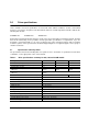
2.8 Power specifications The drive receives DC power (+5V) through a native SATA power connector. See Figure 2 on page 20. 2.8.1 Power consumption Power requirements for the drives are listed in the table on page 9. Typical power measurements are based on an average of drives tested, under nominal conditions, using +5V input voltage at 35°C ambient temperature.
Table 2: 200GB DC power requirements Parameter Regulation Voltage 200Gb (3.0GB) +/‐5% +5 V Current (A) Power (W) DCx 0.15 0.75 DCx 0.11 0.55 DCx 0.11 0.
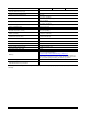
Table 3: 100GB DC power requirements Parameter Regulation Voltage 100Gb (3.0GB) +/‐5% +5 V Current (A) Power (W) DCx 0.14 0.70 DCx 0.11 0.55 DCx 0.10 0.
Table 4: 50GB DC power requirements Parameter Regulation Voltage 50Gb (3.0GB) +/‐5% +5 V Current (A) Power (W) DCx 0.13 0.65 DCx 0.11 0.55 DCx 0.09 0.
2.8.1.1 Typical current profiles Figure 1. Typical 5V startup and operation current profile 2.8.2 Conducted noise Input noise ripple is measured at the host system power supply across an equivalent 15-ohm resistive load on the +5 volt line. • Using 5-volt power, the drive is expected to operate with a maximum of 250 mV peak-to-peak sine-wave injected noise at a frequency from 100Hz up to 20 MHz. Note.
2.9 Environmental specifications 2.9.1 Ambient temperature Ambient temperature is defined as the temperature of the environment immediately surrounding the drive. Actual drive case temperature should not exceed 60°C (140°F) within the operating ambient conditions. Above 1000 feet (305 meters), the maximum temperature is derated linearly to 112°F (44°C) at 10,000 feet (3,048 meters). Operating: 5° to 60°C (41° to 140°F) Nonoperating: –40° to 70°C (–40° to 158°F) 2.9.
2.9.6 Vibration All vibration specifications assume that the drive is mounted securely with the input vibration applied at the drive mounting screws. Vibration may be applied in the X, Y or Z axis. 2.9.6.1 Operating vibration The maximum random vibration levels that the drive may experience while meeting the performance standards specified in this document are specified below. This specification does not cover connection issues that may result from testing at this level. 20–2000 Hz 2.9.6.
2.11 Reliability 2.11.1 Annualized Failure Rate (AFR) and Mean Time Between Failures (MTBF) The product shall achieve an Annualized Failure Rate - AFR - of 0.44%. AFR and MTBF are population statistics that are not relevant to individual units. AFR and MTBF specifications are based on the following assumptions: • 8760 power-on-hours per year. • 250 average power cycles per year. • Operations at nominal voltages.
2.12 Agency certification 2.12.1 Safety certification These products are certified to meet the requirements of UL60950-1, CSA60950-1 and EN60950 and so marked as to the certify agency. 2.12.2 Electromagnetic compatibility Drives that display the CE mark comply with the European Union (EU) requirements specified in the Electromagnetic Compatibility Directive (2004/108/EC) as put into place 20 July 2007.
Radio and television interference. This equipment generates and uses radio frequency energy and if not installed and used in strict accordance with the manufacturer’s instructions, may cause interference to radio and television reception. This equipment is designed to provide reasonable protection against such interference in a residential installation. However, there is no guarantee that interference will not occur in a particular installation.
"X" indicates the hazardous and toxic substance content of the part (at the homogenous material level) is over the threshold defined by the China RoHS MCV Standard. X "表示该部件(于同类物品程度上)所含的危险和有毒物质超出中国RoHS MCV标准所定义的门槛值。 2.14 Corrosive environment Seagate electronic drive components pass accelerated corrosion testing equivalent to 10 years exposure to light industrial environments containing sulfurous gases, chlorine and nitric oxide, classes G and H per ASTM B845.
3.0 Configuring and mounting the drive This section contains the specifications and instructions for configuring and mounting the drive. 3.1 Handling and static-discharge precautions After unpacking, and before installation, the drive may be exposed to potential handling and electrostatic discharge (ESD) hazards.
3.2 Configuring the drive Each drive on the Serial ATA interface connects point-to-point with the Serial ATA host adapter. There is no master/slave relationship because each drive is considered a master in a point-to-point relationship. If two drives are attached on one Serial ATA host adapter, the host operating system views the two devices as if they were both “masters” on two separate ports. Both drives behave as if they are Device 0 (master) devices.
3.4 Drive mounting You can mount the drive in any orientation using four screws in the side-mounting holes or four screws in the bottom-mounting holes. See Figure 3 for drive mounting dimensions. Follow these important mounting precautions when mounting the drive: • Allow a minimum clearance of 0.030 in (0.76 mm) around the entire perimeter of the drive for cooling as a guideline. Please refer to Section 3.5 for final cooling requirements. • Use only M3 x 0.5 metric mounting screws. • Four (4) threads (0.
3.5 Cooling Cabinet cooling must be designed by the customer so that the ambient temperature immediately surrounding the drive will not exceed temperature conditions specified in Section 2.9.1, "Ambient temperature." The rack, cabinet, or drawer environment for the drive must provide heat removal. You should confirm that adequate heat removal is provided using the temperature measurement guidelines described in Section 2.9.1.
4.0 Serial ATA (SATA) interface These drives use the industry-standard Serial ATA interface that supports FIS data transfers. It supports ATA programmed input/output (PIO) modes 0–4; multiword DMA modes 0–2, and Ultra DMA modes 0–6. For detailed information about the Serial ATA interface, refer to the “Serial ATA: High Speed Serialized AT Attachment” specification. 4.
4.2 Serial ATA device plug connector pin definitions Table 6 summarizes the signals on the Serial ATA interface and power connectors.
4.3 Supported ATA commands The following table lists Serial ATA standard commands that the drive supports. For a detailed description of the ATA commands, refer to the Serial ATA: High Speed Serialized AT Attachment specification. See “S.M.A.R.T. commands” on page 35.for details and subcommands used in the S.M.A.R.T. implementation.
Command name Command code (in hex) Note: Individual Set Max Address commands are identified by the value placed in the Set Max Features register as defined to the right. Address: Password: Lock: Unlock: Freeze Lock: Set Max Address Extended 37H Set Multiple Mode C6H Sleep E6H S.M.A.R.T. Disable Operations B0H / D9H S.M.A.R.T. Enable/Disable Autosave B0H / D2H S.M.A.R.T. Enable Operations B0H / D8H S.M.A.R.T. Execute Offline B0H / D4H S.M.A.R.T. Read Attribute Thresholds B0H / D1H S.M.A.
4.3.1 Identify Device command The Identify Device command (command code ECH) transfers information about the drive to the host following power up. The data is organized as a single 512-byte block of data, whose contents are shown in Table 7 on page 25. All reserved bits or words should be set to zero. Parameters listed with an “x” are drive-specific or vary with the state of the drive. See Section 2.0 on page 3 for default parameter settings.
Word Description Value 64 Advanced PIO modes supported. SATA = 0003h 0003H 65 Minimum Multiword DMA transfer cycle time per word (120ns) 0078H 66 Recommended Multiword DMA transfer cycle time (120ns) 0078H 67 Minimum PIO transfer cycle time without flow control (120ns) 0078H 68 Minimum PIO transfer cycle time with IORDY flow control (120ns) 0078H 69 Additional Features and Commands supported.
Word Description Value 112–115 Reserved 0000H 116 Reserved for TLC 0000H 117–118 Logical sector size (DWord) 0000H 119 Commands and feature sets supported 4010H 120 Commands and feature sets supported or enabled 4010H 121–126 Reserved for expanded supported and enabled settings 0000H 127 Obsolete 0000H 128 Security status 0001H 129–159 Vendor specific 0000H 160–167 Reserved for the CompactFlash Association 0000H 168 Device Nominal Form Factor 0000H 169 DATA SET MANAGEMEN
Note. See the bit descriptions below for words 49, 50, 69, 76, 78, 82-86, 119 and 119-120 of the Identify Drive data.
6 Device supports Software Settings Preservation 7-15 Reserved for Serial ATA Bit Word 82 0 The SMART feature set is supported 1 The Security feature set is supported 2 Obsolete 3 Mandatory Power Management feature set is supported 4 PACKET feature set is supported 5 Volatile write cache is supported 6 Read look-ahead is supported 7 Release interrupt is supported 8 SERVICE interrupt is supported 9 DEVICE RESET command is supported 10 HPA feature set is supported 11 Obsolete 12
32 2 Media serial number is supported 3 Media Card Pass Through Command feature set is supported 4 Streaming feature set is supported 5 GPL feature set is supported 6 WRITE DMA FUA EXT and WRITE MULTIPLE FUA EXT commands are supported 7 Obsolete 8 64-bit World wide name is supported 9-10 Obsolete 11-12 Reserved for TLC 13 IDLE IMMEDIATE command with UNLOAD feature is supported 14 Shall be set to one 15 Shall be cleared to zero Bit Word 85 9 DEVICE RESET command is not supported
14 Shall be set to one 15 Shall be cleared to zero Bit Word 119 0 Reserved 1 Write-Read-Verify feature set is supported 2 WRITE UNCORRECTABLE EXT command is supported 3 READ LOG DMA EXT and WRITE LOG DMA EXT commands are supported 4 DOWNLOAD MICROCODE command with mode 3 is supported 5 Free-fall Control feature set is supported 6 Extended Status Reporting feature set is supported 7 Extended Power Conditions feature set is supported 8-13 Reserved 14 Shall be set to one 15 Shall be
4.3.2 Set Features command This command controls the implementation of various features that the drive supports. When the drive receives this command, it sets BSY, checks the contents of the Features register, clears BSY and generates an interrupt. If the value in the register does not represent a feature that the drive supports, the command is aborted. Power-on default has the read look-ahead and write caching features enabled.
4.3.3 S.M.A.R.T. commands S.M.A.R.T. provides near-term failure prediction for drives. When S.M.A.R.T. is enabled, the drive monitors predetermined drive attributes that are susceptible to degradation over time. If self-monitoring determines that a failure is likely, S.M.A.R.T. makes a status report available to the host. Not all failures are predictable. S.M.A.R.T. predictability is limited to the attributes the drive can monitor. For more information on S.M.A.R.T.
36 Pulsar Product Manual, Rev.
5.0 Seagate Technology support services Online services Web For information regarding Seagate products and services, visit www.seagate.com. Worldwide support is available 24 hours daily by email for your questions. Warranty Support: http://www.seagate.com/www/en-us/support/warranty_&_returns_assistance direct.seagate.com direct.seagate.com is the industry's first Web portal designed specifically for OEMs and distributors.
Customer Service Operations Presales Support Our Presales Support staff can help you determine which Seagate products are best suited for your specific application or computer system, as well as product availability and compatibility. Technical Support Seagate technical support is available to assist you online at support.seagate.com or through one of our call centers. Have your system configuration information and your "ST" model/product number available.
Index A ACA 16 acceleration 14 Access time 7 Agency certification 16 altitude 13 Ambient temperature 13 ambient temperature 7, 8 Annualized Failure Rate (AFR) 15 ATA commands 25 Australia/New Zealand Standard AS/NZ CISPR22 16 Australian Communication Authority (ACA) 16 Australian C-Tick 16 Average latency 7 Average seek time 7 C cables and connectors 20 capacity 5 case temperature 13 CE mark 16 certification 16 Check Power Mode 25 China RoHS directive 17 Class B computing device 16 compatibility 16 Conduct
L latency 7 LBA mode 5 length 6 logical geometry 5 M maintenance 15 master/slave 2 maximum temperature 13 mounting 21 mounting screws 13 mounting the drive 19 Read Native Max Address Extended 25 Read Sectors 25 Read Sectors Extended 25 Read Verify Sectors 25 Read Verify Sectors Extended 25 Read/write heads 5 Recording technology 5 relative humidity 13 Reliability 15 RF 14 RMS read/write current 12 RoHS 17 RRL 16 S N noise 12 nominal power 7 Nonoperating shock 13 Nonoperating vibration 14 O Operating sho
T technical support services 37 temperature 7, 13 temperature gradient 13 Time to Ready 7 U UL60950-1 16 V Vibration 14 voltage 8 Voltage dips, interrupts 14 Voltage tolerance 12 W weight 6 wet bulb temperature 13 width 6 Write Buffer 26 Write DMA 26 Write DMA Extended 26 Write DMA FUA Extended 26 Write FPDMA queued 26 Write Log Extended 26 Write Multiple 26 Write Multiple Extended 26 Write Multiple FUA Extended 26 Write Sectors 26 Write Sectors Extended 26 write uncorrectable 26 Pulsar Product Manual,
42 Pulsar Product Manual, Rev.
Seagate Technology LLC 920 Disc Drive, Scotts Valley, California 95066-4544, USA Publication Number: 100596473, Rev.