Product Manual Momentus 7200.4 SATA ST9500420AS ST9500420ASG ST9320423AS ST9320423ASG ST9250410AS ST9250410ASG ST9160412AS ST9160412ASG ST9120410AS ST9120410ASG ST980412AS ST980412ASG 100534376 Rev.
© 2010 Seagate Technology LLC. All rights reserved. Publication number: 100534376, Rev. C, November 2010 Seagate, Seagate Technology and the Wave logo are registered trademarks of Seagate Technology LLC in the United States and/or other countries. Momentus and SeaTools are either trademarks or registered trademarks of Seagate Technology LLC or one of its affiliated companies in the United States and/or other countries.
Contents 1.0 Introduction. . . . . . . . . . . . . . . . . . . . . . . . . . . . . . . . . . . . . . . . . . . . . . . . . . . . . . . . . . . . . . . . . . . 1 1.1 About the Serial ATA interface . . . . . . . . . . . . . . . . . . . . . . . . . . . . . . . . . . . . . . . . . . . . . . 2 2.0 Drive specifications . . . . . . . . . . . . . . . . . . . . . . . . . . . . . . . . . . . . . . . . . . . . . . . . . . . . . . . . . . . . 3 2.1 Specification summary table . . . . . . . . . . . . . . . . . . . .
ii Momentus 7200.4 SATA Product Manual, Rev.
List of Figures Figure 1. Figure 2. Figure 3. Figure 4. Typical +5V only startup and operation current profile . . . . . . . . . . . . . . . . . . . . . . . . . . . . . . . 9 Serial ATA connectors . . . . . . . . . . . . . . . . . . . . . . . . . . . . . . . . . . . . . . . . . . . . . . . . . . . . . . 20 Attaching SATA cabling . . . . . . . . . . . . . . . . . . . . . . . . . . . . . . . . . . . . . . . . . . . . . . . . . . . . . 20 Mounting dimensions—top, side and end view . . . . . . . . . . . . . .
1.0 Introduction This manual describes the functional, mechanical and interface specifications for the following Seagate Momentus® 7200.4 SATA model drives: Standard models Free Fall Protection models ST9500420AS ST9500420ASG ST9320423AS ST9320423ASG ST9250410AS ST9250410ASG ST9160412AS ST9160412ASG ST9120410AS ST9120410ASG ST980412AS ST980412ASG These drives provide the following key features: • 7200-RPM spindle speed. • 16-Mbyte buffer.
1.1 About the Serial ATA interface The Serial ATA interface provides several advantages over the traditional (parallel) ATA interface. The primary advantages include: • Easy installation and configuration with true plug-and-play connectivity. It is not normally necessary to set any jumpers or other configuration options. • Thinner and more flexible cabling for improved enclosure airflow and ease of installation. • Scalability to higher performance levels.
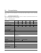
2.0 Drive specifications Unless otherwise noted, all specifications are measured under ambient conditions, at 25°C, and nominal power. 2.1 Specification summary table The specifications listed in this table are for quick reference. For details on specification measurement or definition, see the appropriate section of this manual.
Table 1: Drive specifications Drive specification ST9500420AS ST9320423AS ST9250410AS ST9160412AS ST9120410AS ST980412AS ST9500420ASG ST9320423ASG ST9250410ASG ST9160412ASG ST9120410ASG ST980412ASG Read power (typical) 2.1 watts Write power (typical) 2.2 watts Idle mode, low power (typical) 0.69 watts Standby mode 0.20 watts (typical)*** Sleep mode 0.
2.
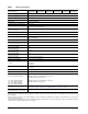
2.5 Recording and interface technology Interface Serial ATA (SATA) Recording method Perpendicular Recording density BPI (bits/inch max) 1490k Track density TPI (tracks/inch max) 265k Areal density (Gbits/inch2 max) 394 Spindle speed (RPM) (± 0.2%) 7200 Maximum Internal transfer rate (Gbits/sec) 1.23 I/O data-transfer rate (Gbits/sec max) 3.0 Interleave 1:1 Cache buffer 16 Mbytes (16,384 kbytes) 2.6 Physical characteristics Drive specification Height (mm) (inches) 9.5 +/-0.2 0.
2.7 Seek time Seek measurements are taken with nominal power at 25°C ambient temperature. All times are measured using drive diagnostics. The specifications in the table below are defined as follows: • Track-to-track seek time is an average of all possible single-track seeks in both directions. • Average seek time is a true statistical random average of at least 5000 measurements of seeks between random tracks, less overhead.
2.9 Power specifications The drive receives DC power (+5V) through a native SATA power connector. 2.9.1 Power consumption Power requirements for the drives are listed in the table on page 8. Typical power measurements are based on an average of drives tested, under nominal conditions, at 25°C ambient temperature. • Spinup power Spinup power is measured from the time of power-on to the time that the drive spindle reaches operating speed.
2.9.1.1 Typical current profile Figure 1. Typical +5V only startup and operation current profile Momentus 7200.4 SATA Product Manual, Rev.
2.9.2 Conducted noise Input noise ripple is measured at the host system power supply across an equivalent 15-ohm resistive load on the +5 volt line. Using 5-volt power, the drive is expected to operate with a maximum of 100 mV peak-to-peak square-wave injected noise at up to 10 MHz. Note. Equivalent resistance is calculated by dividing the nominal voltage by the typical RMS read/write current. 2.9.3 Voltage tolerance Voltage tolerance (including noise): 5V ± 5% 10 Momentus 7200.
2.9.4 Power-management modes The drive provides programmable power management to provide greater energy efficiency. In most systems, you can control power management through the system setup program.
2.10 Environmental specifications This section provides the temperature, humidity, shock, and vibration specifications for Momentus 7200.4 SATA drives. 2.10.1 Ambient temperature Ambient temperature is defined as the temperature of the environment immediately surrounding the drive. Actual drive case temperature should not exceed 65°C (149°F) within the operating ambient conditions. Above 1000 feet (305 meters), the maximum temperature is derated linearly by 1°C every 1000 feet.
2.10.6.2 Nonoperating shock The nonoperating shock level that the drive can experience without incurring physical damage or degradation in performance when subsequently put into operation is 800 Gs based on a nonrepetitive half-sine shock pulse of 2 msec duration. The nonoperating shock level that the drive can experience without incurring physical damage or degradation in performance when subsequently put into operation is 1000 Gs based on a nonrepetitive half-sine shock pulse of 1 msec duration.
2.
2.14 Agency certification 2.14.1 Safety certification The drives are recognized in accordance with UL 60950-1 and CSA C22.2 (950) and meet all applicable sections of IEC 60950-1 and EN60950-1 as tested by TUV North America. 2.14.2 Electromagnetic compatibility Hard drives that display the CE mark comply with the European Union (EU) requirements specified in the Electromagnetic Compatibility Directive (89/336/EEC).
This equipment is designed to provide reasonable protection against such interference in a residential installation. However, there is no guarantee that interference will not occur in a particular installation. If this equipment does cause interference to radio or television, which can be determined by turning the equipment on and off, you are encouraged to try one or more of the following corrective measures: • Reorient the receiving antenna. • Move the device to one side or the other of the radio or TV.
2.15 Environmental protection Seagate designs its products to meet environmental protection requirements worldwide, including regulations restricting certain chemical substances. 2.15.1 European Union Restriction of Hazardous Substances (RoHS) Seagate designs its products to meet environmental protection requirements worldwide, including regulations restricting certain chemical substances.
2.16 Corrosive environment Seagate electronic drive components pass accelerated corrosion testing equivalent to 10 years exposure to light industrial environments containing sulfurous gases, chlorine and nitric oxide, classes G and H per ASTM B845. However, this accelerated testing cannot duplicate every potential application environment.
3.0 Configuring and mounting the drive This section contains the specifications and instructions for configuring and mounting the drive. 3.1 Handling and static-discharge precautions After unpacking, and before installation, the drive may be exposed to potential handling and electrostatic discharge (ESD) hazards.
3.2 Configuring the drive Each drive on the Serial ATA interface connects in a point-to-point configuration with the Serial ATA host adapter. There is no master/slave relationship because each drive is considered a master in a point-to-point relationships. If two drives are attached on one Serial ATA host adapter, the host operating system views the two devices as if they were both “masters” on two separate ports. This means both drives behave as if they are Device 0 (master) devices.
3.4 Drive mounting You can mount the drive using four screws in the side-mounting holes or four screws in the bottom-mounting holes. See Figure 4 for drive mounting dimensions. Follow these important mounting precautions when mounting the drive: • Allow a minimum clearance of 0.030 inches (0.76 mm) around the entire perimeter of the drive for cooling. • Use only M3 UNC mounting screws. • Do not overtighten the mounting screws (maximum torque: 4.0 inch-lb). • Four (4) threads (0.
4.0 Serial ATA (SATA) interface These drives use the industry-standard Serial ATA interface that supports FIS data transfers. It supports ATA programmed input/output (PIO) modes 0–4; multiword DMA modes 0–2, and Ultra DMA modes 0–6. The drive also supports the use of the IORDY signal to provide reliable high-speed data transfers. For detailed information about the Serial ATA interface, refer to the “Serial ATA: High Speed Serialized AT Attachment” specification. 4.
4.2 Serial ATA device plug connector pin definitions Table 7 summarizes the signals on the Serial ATA interface and power connectors.. Table 7: Segment Signal Serial ATA connector pin definitions Pin Function Definition S1 Ground 2nd mate S2 A+ Differential signal pair A from Phy S3 A- S4 Ground 2nd mate S5 B- Differential signal pair B from Phy S6 B+ S7 Ground 2nd mate Key and spacing separate signal and power segments Power P1 V33 3.3V power P2 V33 3.3V power P3 V33 3.
4.3 Supported ATA commands The following table lists Serial ATA standard commands that the drive supports. For a detailed description of the ATA commands, refer to the Serial ATA: High Speed Serialized AT Attachment specification. See “S.M.A.R.T. commands” on page 31.for details and subcommands used in the S.M.A.R.T. implementation.
Command name Command code (in hex) Note: Individual Set Max commands are identified by the value placed in the Set Max Features register as defined to the right. Address: Password: Lock: Unlock: Freeze Lock: Set Multiple Mode C6h S.M.A.R.T. Disable Operations B0h/D9h S.M.A.R.T. Enable/Disable Autosave B0h/D2h S.M.A.R.T. Enable Operations B0h/D8h S.M.A.R.T. Enable/Disable Auto Offline B0h/DBh S.M.A.R.T. Enable One Attribute Modification B0h/E0h S.M.A.R.T. Execute Offline B0h/D4h S.M.A.R.T.
Command name Command code (in hex) Standby Immediate E0h ATA-standard security commands Security Set Password F1h Security Unlock F2h Security Erase Prepare F3h Security Erase Unit F4h Security Freeze Lock F5h Security Disable Password F6h 4.3.1 Identify Device command The Identify Device command (command code ECH) transfers information about the drive to the host following power up. The data is organized as a single 512-byte block of data, whose contents are shown in the table on page 27.
Word Description Value 27–46 Drive model number: (40 ASCII characters, padded with blanks to end of string) ST9500420AS ST9500420ASG ST9320423AS ST9320423ASG ST9250410AS ST9250410ASG ST9160412AS ST9160412ASG ST9120410AS ST9120410ASG ST980412AS ST980412ASG 47 (Bits 7–0) Maximum sectors per interrupt on Read multiple and Write multiple (16) 8010H 48 Reserved 0000H 49 Standard Standby timer, IORDY supported and may be disabled 2F00H 50 ATA-reserved 0000H 51 PIO data-transfer cycle timing mod
Word Description Value 69–74 ATA-reserved 0000H 75 Queue depth 0000H 76 Serial ATA capabilities 0508H 77 ATA-reserved 0000H 78 Serial ATA features supported 0048H 79 Serial ATA features enabled 0040H 80 Major version number 003EH 81 Minor version number 0000H 82 Command sets supported 306BH 83 Command sets supported 4001H 84 Command sets support extension 61E3H 85 Command sets enabled 30xxH 86 Command sets enabled 0001H 87 Command sets enable extension 4000H 88
Word Description Value 129– 159 Seagate-reserved xxxxH 160– 254 ATA-reserved 0000H 255 Integrity word xxA5H Note. See the bit descriptions below for words 63, 88, 93 and 94 of the Identify Drive data: Description (if bit is set to 1) Bit Word 63 0 Multiword DMA mode 0 is supported. 1 Multiword DMA mode 1 is supported. 2 Multiword DMA mode 2 is supported. 8 Multiword DMA mode 0 is currently active. 9 Multiword DMA mode 1 is currently active.
4.3.2 Set Features command This command controls the implementation of various features that the drive supports. When the drive receives this command, it sets BSY, checks the contents of the Features register, clears BSY and generates an interrupt. If the value in the register does not represent a feature that the drive supports, the command is aborted. Power-on default has the read look-ahead and write caching features enabled.
4.3.3 S.M.A.R.T. commands S.M.A.R.T. provides near-term failure prediction for disc drives. When S.M.A.R.T. is enabled, the drive monitors predetermined drive attributes that are susceptible to degradation over time. If self-monitoring determines that a failure is likely, S.M.A.R.T. makes a status report available to the host. Not all failures are predictable. S.M.A.R.T. predictability is limited to the attributes the drive can monitor. For more information on S.M.A.R.T.
5.0 Seagate Technology support services SEAGATE ONLINE SUPPORT and SERVICES For information regarding products and services, visit http://www.seagate.com/www/en-us/about/contact_us/ Available services include: Presales & Technical support Global Support Services telephone numbers & business hours Authorized Service Centers For information regarding Warranty Support, visit http://www.seagate.
Index A ACA 15 acoustics 4, 13 Active mode 11 Address 24 AFR 14 Agency certification 15 Altitude 12 Altitude, nonoperating 4 Altitude, operating 4 Ambient temperature 4, 12 ambient temperature 7 Annualized Failure Rate 14 Annualized Failure Rate (AFR) 4 Areal density 3, 6 ATA commands 24 ATA data-transfer modes supported 3 Australia/New Zealand Standard AS/NZS3548 1995 15 Australian Communication Authority (ACA) 15 Australian C-Tick 15 Average seek time 7 Average seek, read 3 B bels 4 BPI 3 buffer 3, 6 Byt
guaranteed sectors 5 N H noise 10 nominal power 7 Nonoperating shock 13 Nonoperating vibration 13 Nonrecoverable read errors 4 nonrecoverable read errors 14 handling 19 Handling precautions 19 heads 5 Height 3 height 6 humidity 4 I I/O data-transfer rate 3, 6 Identify 24 Identify Device 24 Identify Device command 26 Idle 8, 25 Idle and Standby timers 11 Idle Immediate 25 Idle mode 4, 11 Idle mode power 8 IEC950 15 Information Technology Equipment (ITE) 15 Initialize Device Parameters 24 Input noise rip
Read/write heads 5 Read/write power 4 read/write power and current 8 Recording density 3, 6 Recording method 6 Recording technology 6 Relative humidity 4, 12 Reliability 14 resistance 10 Retries 24 RF 14 RoHS 17 RPM 3 RRL 15 S S.M.A.R.T. 25 S.M.A.R.T.
36 Momentus 7200.4 SATA Product Manual, Rev.
Seagate Technology LLC 920 Disc Drive, Scotts Valley, California 95066-4544, USA Publication Number: 100534376, Rev.