
Computer Drive - DVD/CD Drive User Manual
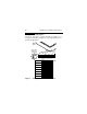
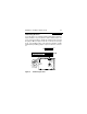
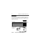

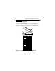
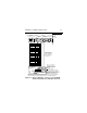
Table Of Contents
- Preface
- Electromagnetic susceptibility
- Electromagnetic compliance
- Electromagnetic compliance for the European Union
- Australian C-Tick
- Seagate Technology support services
- General description
- Initial setup information
- General information
- SCSI ID jumpers
- Drive termination
- Terminator power
- I/O circuits and data path widths
- Providing adequate cooling
- Mounting the drive and connecting cables
- Formatting the drive
- Quick reference desktop system notes
- Setting the SCSI ID jumpers
- Terminating the drive
- Terminator power
- Other applicable jumper options
- Setting the SCSI ID jumpers
- Terminating the drive
- Terminator power
- Other applicable jumper options
- Setting the SCSI ID jumpers
- Terminating the drive
- Applicable jumper options
Medalist Pro Installation Guide, Rev. B 47
W/LW drives
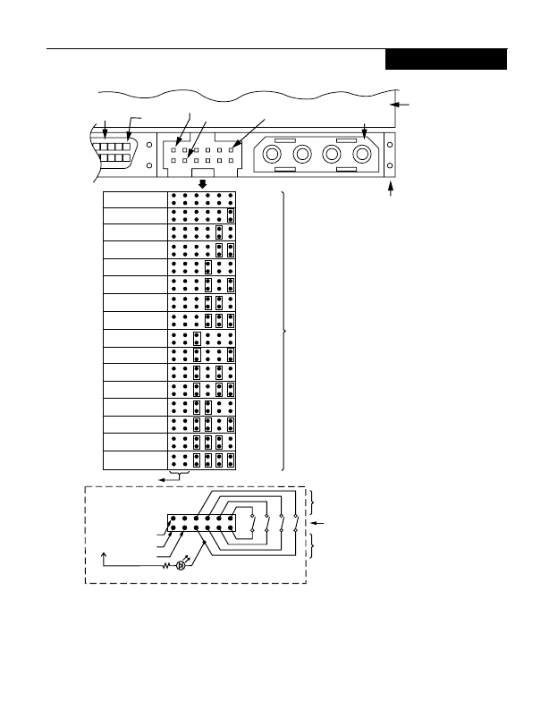
Figure 12. Using J1-Auxillary connector for model W/LW
drives alternate ID select and LED connection
J1-DC Power
J1
68 Pin SCSI I/O
Connector
Drive
HDA
Rear
SCSI ID = 8
SCSI ID = 9
SCSI ID = 10
SCSI ID = 11
SCSI ID = 12
SCSI ID = 13
SCSI ID = 14
SCSI ID = 15
A
not used
3
A
2
A
1
SCSI ID = 0
SCSI ID = 1
SCSI ID = 2
SCSI ID = 3
SCSI ID = 4
SCSI ID = 5
SCSI ID = 6
SCSI ID = 7
A
0
J1-Auxiliary
Pin 1A
4P 3P2P 1P
PCB
Pin 1
+5V
Ground
(default)
A
0
A
1
A
2
A
3
1197531
12 10 8 6 4 2
Host Alternate
Usage Plug
Pins 1, 3, 5, and 7 are
optional connections to
switching circuits in host
equipment to establish
drive ID.
Remote Switches
For ID selection use
jumpers as shown or
connect a cable for
remote switching as
shown below.
Dashed area is optional host circuitry (external to the
drive) connected to host supplied optional usage plug.
+5V
Drive Activity LED
+5V
N.C.
Ground
Pins 2, 4, 6, and 8 are normally
not grounded. They are driven low
(ground) for 250 ms after a Reset or
PWR ON to allow drive to read
SCSI ID selected. Pin 8 may
also be used to drive the cathode
of an external Activity LED.