
Computer Drive - DVD/CD Drive User Manual
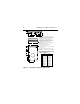
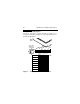

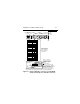
Table Of Contents
- Preface
- Electromagnetic susceptibility
- Electromagnetic compliance
- Electromagnetic compliance for the European Union
- Australian C-Tick
- Seagate Technology support services
- General description
- Initial setup information
- General information
- SCSI ID jumpers
- Drive termination
- Terminator power
- I/O circuits and data path widths
- Providing adequate cooling
- Mounting the drive and connecting cables
- Formatting the drive
- Quick reference desktop system notes
- Setting the SCSI ID jumpers
- Terminating the drive
- Terminator power
- Other applicable jumper options
- Setting the SCSI ID jumpers
- Terminating the drive
- Terminator power
- Other applicable jumper options
- Setting the SCSI ID jumpers
- Terminating the drive
- Applicable jumper options
40 Medalist Pro Installation Guide, Rev. B
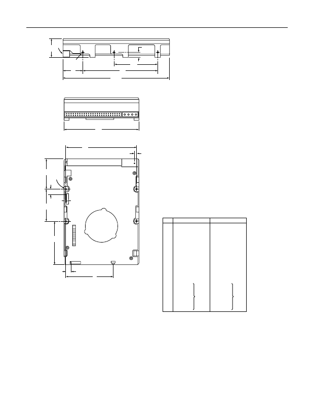
Figure 6. Mounting configuration dimensions
Inches
A
B
C
D
E
F
G
H
J
K
L
M
N
P
R
S
146.99
102.2
26.9
60.00
28.45
101.60
6.35
44.45
95.25
41.28
3.63
6.60
1.55
10.29
57.53
59.69
5.787
4.023
1.28
2.362
1.120
4.000
.250
1.750
3.750
1.625
0.143
0.260
0.061
0.405
2.265
2.350
± .010
± .010
+ .021
– .009
± .010
± .020
± .010
+ .010
– .005
± .010
± .010
± .020
± .25
± .25
+ .53
– .22
± .25
± .51
± .25
+ .25
– .12
± .25
± .25
± .51
Dimension Table
Millimeters
[7]
Mounting holes three on each side, 6-32 UNC. Max
screw length into side of drive 0.15 in. (3.81 mm). Screw
tightening torque 6.0 in-lb (.675 NM) max with minimum
thread engagement of 0.12 in. (3.05 mm).
Mounting holes four on bottom, 6-32 UNC. Max screw
length into bottom of drive 0.15 in. (3.81 mm). Screw
tightening torque 6.0 in-lb (.675 NM) max with minimum
thread engagement of 0.12 in. (3.05 mm).
Power and interface connectors can extend past the “A”
dimension by 0.040 in. (1.02 mm).
Centerline of pad for Pin 1 of power connector.
Centerline of pad for Pin 1 of J6.
Centerline of pad for Pin 1 of J2. Dimensions indicated are
for reference only.
Dimensions to Pin 1 of each connector are nominal values.
To pin ends on J6. Pin ends on J6 are nominally flush with
end of drive.
Although the illustration shows the 50 pin I/O connector
drive model, mounting hole locations are the same for
all Medalist Pro models.
Notes:
[1]
[2]
[3]
[4]
[5]
[6]
[7]
[8]
[9]
B
J
[4] L
H
M [6]
[6] N
J2
J6 LED
K
S [8]
[2]
R
P [5]
[7]
A [3]
F
D
[1]
[3]
G
C
E