
Computer Drive - DVD/CD Drive User Manual
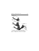
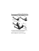
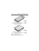

Table Of Contents
- Preface
- Electromagnetic susceptibility
- Electromagnetic compliance
- Electromagnetic compliance for the European Union
- Australian C-Tick
- Seagate Technology support services
- General description
- Initial setup information
- General information
- SCSI ID jumpers
- Drive termination
- Terminator power
- I/O circuits and data path widths
- Providing adequate cooling
- Mounting the drive and connecting cables
- Formatting the drive
- Quick reference desktop system notes
- Setting the SCSI ID jumpers
- Terminating the drive
- Terminator power
- Other applicable jumper options
- Setting the SCSI ID jumpers
- Terminating the drive
- Terminator power
- Other applicable jumper options
- Setting the SCSI ID jumpers
- Terminating the drive
- Applicable jumper options
Medalist Pro Installation Guide, Rev. B 37
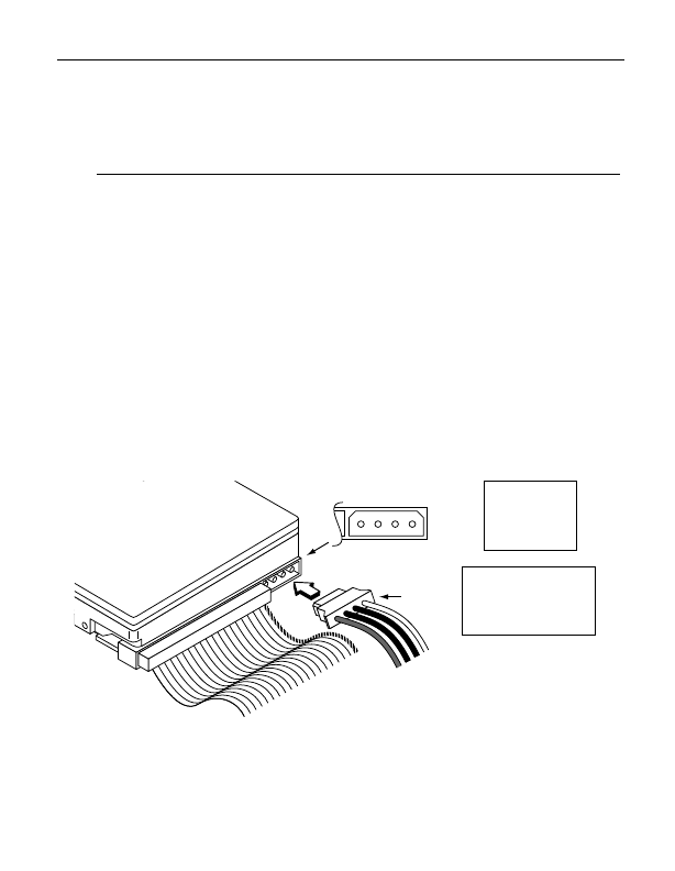
defined in IEC 950. Figure 5 provides the pin information for
the DC power connector. To connect the DC power cable to
the drive, simply insert the cable end into the drive’s DC
power connector.
4. Schließen Sie das SCSI-Kabel an den SCSI-Steckverbinder
des Laufwerkes an. Das Kabel darf nicht gedehnt oder
gedrückt werden und es darf den Luftstrom zur Kühlung des
Systems nicht behindern.
Das Laufwerk wird über einen 4-poligen, neben dem SCSI-
Anschluß befestigten Steckverbinder mit Gleichstrom ver-
sorgt. Der Ausgang eines Netzteils muß SELV (safety extra
low voltage) nach IEC 950 entsprechen. Abbildung 5 zeigt
die Steckerbelegung für den Gleichstromanschluß. Zum
Anschluß des Gleichstromkabels an das Laufwerk das
Kabelende in den Gleichstromanschluß des Laufwerkes
stecken.
Figure 5. DC power connector
Abbildung 5. Gleichstromanschluß
Power
Cable
DC Power
Connector
4 3 2 1
Pin
1
2
3
4
Power
+12V
+12V ret
+ 5V ret
+ 5V
Pin
1
2
3
4
Gleichstrom
+12V
+12V Rückleitung
+ 5V Rückleitung
+ 5V