
Computer Drive - DVD/CD Drive User Manual
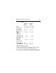
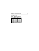
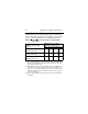
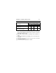
Table Of Contents
- Preface
- Electromagnetic susceptibility
- Electromagnetic compliance
- Electromagnetic compliance for the European Union
- Australian C-Tick
- Seagate Technology support services
- General description
- Initial setup information
- General information
- SCSI ID jumpers
- Drive termination
- Terminator power
- I/O circuits and data path widths
- Providing adequate cooling
- Mounting the drive and connecting cables
- Formatting the drive
- Quick reference desktop system notes
- Setting the SCSI ID jumpers
- Terminating the drive
- Terminator power
- Other applicable jumper options
- Setting the SCSI ID jumpers
- Terminating the drive
- Terminator power
- Other applicable jumper options
- Setting the SCSI ID jumpers
- Terminating the drive
- Applicable jumper options

20 Medalist Pro Installation Guide, Rev. B
±5% must be maintained after the drive signifies that its
power-up sequence has been completed and that the drive is
able to accept selection by the host initiator.
[3] See the +12V current profile in the
Medalist Pro Product
Manual
(publication number 32661-001).
[4] This condition occurs when the Motor Start option is enabled
and the drive has not yet received a Start Motor command.
[5] See “Conducted noise immunity” in the
Medalist Pro Product
Manual.
The specified voltage tolerance is inclusive of ripple,
noise, and transient response.
[6] Operating condition is defined as random seek read opera-
tions with a block count of 64.
General Notes for Tables 2a and 2b:
1. Minimum current loading for each supply voltage is not less
than 4% of the maximum operating current shown.
2. Use separate ground returns for +5V and +12V supplies.
3. Where power is provided to multiple drives from a common
supply, carefully consider individual drive power require-
ments. Where multiple units are powered on simultaneously,
be sure the peak starting current is available to each device.