
Computer Drive - DVD/CD Drive User Manual
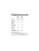
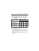
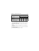
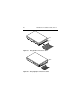
Table Of Contents
- Preface
- Electromagnetic susceptibility
- Electromagnetic compliance
- Electromagnetic compliance for the European Union
- Australian C-Tick
- Seagate Technology support services
- General description
- Initial setup information
- General information
- SCSI ID jumpers
- Drive termination
- Terminator power
- I/O circuits and data path widths
- Providing adequate cooling
- Mounting the drive and connecting cables
- Formatting the drive
- Quick reference desktop system notes
- Setting the SCSI ID jumpers
- Terminating the drive
- Terminator power
- Other applicable jumper options
- Setting the SCSI ID jumpers
- Terminating the drive
- Terminator power
- Other applicable jumper options
- Setting the SCSI ID jumpers
- Terminating the drive
- Applicable jumper options

Medalist Pro Installation Guide, Rev. B 19
Table 2b. DC power requirements (Amps) for LW/LC
models
Notes for Tables 2a and 2b.
[1] Measured with an average reading DC ammeter. Instanta-
neous +12V current peaks will exceed these values.
[2] A –10% droop is permissible during initial start of the spindle
but must return to ±5% before reaching 7,200 RPM. The
ST39140
LW/LC
ST34520
LW/LC
Voltage +5V +12V +5V +12V
Regulation [5] ±5% ±5%[2] ±5% ±5%[2]
Max. operating
current DC [1] 0.81 2.4 0.81 2.4
Avg. idle current
DCX
[1] 0.53 0.90 0.53 0.90
Max. starting
current
(peak DC) DC [3]
(peak AC) AC [3]
2.5
N/A
2.5
N/A
Delayed motor
start (max)
DC [1][4] 0.51 0.16 0.51 0.16
Peak operating
current
Typical DCX
[1][6]
Maximum DC [1]
0.58
0.81
1.0
1.53
0.58
0.81
1.0
1.37