Product Manual ® Constellation CS Serial ATA Standard Models ST3000NC002 ST2000NC001 ST1000NC001 100695091 Rev.
Document Revision History Revision Date Description of Change Rev. A 07/18/2012 Initial release. Rev. B 10/05/2012 8-10 & 18. Rev. C 11/13/2012 5, 16 & 19. © 2012 Seagate Technology LLC. All rights reserved. Publication number: 100695091, Rev. C November 2012 Seagate, Seagate Technology and the Wave logo are registered trademarks of Seagate Technology LLC in the United States and/ or other countries.
Contents Seagate® Technology Support Services . . . . . . . . . . . . . . . . . . . . . . . . . . . . . . . . . . . . . . . . . . . . . . . . . 1 1.0 Introduction. . . . . . . . . . . . . . . . . . . . . . . . . . . . . . . . . . . . . . . . . . . . . . . . . . . . . . . . . . . . . . . . . . . 2 1.1 About the SATA interface . . . . . . . . . . . . . . . . . . . . . . . . . . . . . . . . . . . . . . . . . . . . . . . . . . 3 2.0 Drive Specifications . . . . . . . . . . . . . . . . . . . . . . . . . . . .
Contents 5.0 SATA Interface . . . . . . . . . . . . . . . . . . . . . . . . . . . . . . . . . . . . . . . . . . . . . . . . . . . . . . . . . . . . . . . 5.1 Hot-Plug compatibility . . . . . . . . . . . . . . . . . . . . . . . . . . . . . . . . . . . . . . . . . . . . . . . . . . . . 5.2 SATA device plug connector pin definitions . . . . . . . . . . . . . . . . . . . . . . . . . . . . . . . . . . . 5.3 Supported ATA commands . . . . . . . . . . . . . . . . . . . . . . . . . . . . . . . . . . . . . . . . .
Figures Figure 1 Figure 2 Figure 3 Figure 4 Figure 5 Figure 6 Figure 7 Typical 3TB model 5V - 6Gb/s startup and operation current profile . . . . . . . . . . . . . . . . . . . 9 Typical 3TB model 12V - 6Gb/s startup and operation current profile . . . . . . . . . . . . . . . . . . 9 Typical 2TB model 12V - 6Gb/s startup and operation current profiles . . . . . . . . . . . . . . . . 10 Typical 1TB model 12V - 6Gb/s startup and operation current profiles . . . . . . . . . . . . . . . .
Seagate® Technology Support Services For information regarding online support and services, visit http://www.seagate.com/about/contact-us/technical-support/ Available services include: • Presales & Technical support • Global Support Services telephone numbers & business hours • Authorized Service Centers For information regarding Warranty Support, visit http://www.seagate.com/support/warranty-and-returns/ For information regarding data recovery services, visit http://www.seagate.
www.seagate.com 1.0 Introduction This manual describes the functional, mechanical and interface specifications for the following Seagate Constellation® CS Serial ATA model drives: Model Number Seagate Instant Secure Erase (ISE) ST3000NC002 No ST3000NC000 Yes ST2000NC001 No ST2000NC000 Yes ST1000NC001 No ST1000NC000 Yes These drives provide the following key features: • 7200 RPM spindle speed.
www.seagate.com 1.1 About the SATA interface The Serial ATA (SATA) interface provides several advantages over the traditional (parallel) ATA interface. The primary advantages include: • Easy installation and configuration with true plug-and-play connectivity. It is not necessary to set any jumpers or other configuration options. • Thinner and more flexible cabling for improved enclosure airflow and ease of installation. • Scalability to higher performance levels.
www.seagate.com 2.0 Drive Specifications Unless otherwise noted, all specifications are measured under ambient conditions, at 25°C, and nominal power. For convenience, the phrases the drive and this drive are used throughout this manual to indicate the following drive models: Standard models Seagate In(SED) models ST3000NC002 ST3000NC000 ST2000NC001 ST2000NC000 ST1000NC001 ST1000NC000 2.1 Specification summary tables The specifications listed in Table 1.
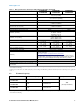
www.seagate.com Table 1 Drive specifications summary for 3TB, 2TB and 1TB models (Continued) ST3000NC002 ST2000NC001 Drive Specification* ST3000NC000 ST2000NC000 ST1000NC001 ST1000NC000 20°C (operating) 30°C (non-operating) Temperature gradient (°C per hour max) 5% to 90% (operating) 5% to 95% (non-operating) Relative humidity Relative humidity gradient (per hour max) 30% Altitude, operating –304.80 m to 3048 m (–1000 ft to 10,000+ ft) Altitude, non-operating (below mean sea level, max) –304.
www.seagate.com 2.2.1 LBA mode When addressing these drives in LBA mode, all blocks (sectors) are consecutively numbered from 0 to n–1, where n is the number of guaranteed sectors as defined above. See Section 5.3.1, "Identify Device command" (words 60-61 and 100-103) for additional information about 48-bit addressing support of drives with capacities over 137GB. 2.
www.seagate.com 2.6 Seek time Seek measurements are taken with nominal power at 25°C ambient temperature. All times are measured using drive diagnostics. The specifications in the table below are defined as follows: • Track-to-track seek time is an average of all possible single-track seeks in both directions. • Average seek time is a true statistical random average of at least 5000 measurements of seeks between random tracks, less overhead. Typical seek times (ms) Read Write Track-to-track 0.5 0.
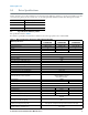
www.seagate.com Table 2: 3TB Drive DC power requirements 3.0Gb mode 6.0Gb mode Voltage +5V +12V +5V +12V Regulation ±5% ±5% ±5% ±5% Avg Idle Current * 0.28 0.34 0.29 0.34 Idle_A 0.17 0.34 0.18 0.34 Idle_B 0.15 0.30 0.16 0.30 Idle_C 0.15 0.19 0.16 0.19 Standby 0.12 0.01 0.13 0.01 0.12 0.01 0.13 0.01 Advanced Idle Current * Average Sleep Current Maximum Start Current DC (peak DC) 3σ 0.45 1.16 0.45 1.16 AC (peak DC) 3σ 0.68 1.94 0.70 1.95 3σ 0.13 0.
www.seagate.com 2.8.1.1 Typical current profiles 3TB model current profile Figure 1 Typical 3TB model 5V - 6Gb/s startup and operation current profile Figure 2 Typical 3TB model 12V - 6Gb/s startup and operation current profile Constellation CS Serial ATA Product Manual, Rev.
www.seagate.com 2TB model current profile Typical 2TB model 5V - 6Gb/s startup and operation current profiles Figure 3 Typical 2TB model 12V - 6Gb/s startup and operation current profiles Constellation CS Serial ATA Product Manual, Rev.
www.seagate.com 1TB model current profile Typical 1TB model 5V - 6Gb/s startup and operation current profiles Figure 4 Typical 1TB model 12V - 6Gb/s startup and operation current profiles Constellation CS Serial ATA Product Manual, Rev.
www.seagate.com 2.8.2 Conducted noise Input noise ripple is measured at the host system power supply across an equivalent 80-ohm resistive load on the +12 volt line or an equivalent 15-ohm resistive load on the +5 volt line. • Using 12-volt power, the drive is expected to operate with a maximum of 120 mV peak-to-peak square-wave injected noise at up to 10MHz. • Using 5-volt power, the drive is expected to operate with a maximum of 100 mV peak-to-peak square-wave injected noise at up to 10MHz.
www.seagate.com 2.8.4 Power-management modes The drive provides programmable power management to provide greater energy efficiency. In most systems, you can control power management through the system setup program.
www.seagate.com 2.8.4.1 Extended Power Conditions - PowerChoiceTM Utilizing the load/unload architecture a programmable power management interface is provided to tailor systems for reduced power consumption and performance requirements. The table below lists the supported power conditions available in PowerChoice.
www.seagate.com PowerChoice Manufacture Default Power Condition Timer Values Default power condition timer values have been established to assure product reliability and data integrity. A minimum timer value threshold of two minutes ensures the appropriate amount of background drive maintenance activities occur. Attempting to set a timer values less than the specified minimum timer value threshold will result in an aborted EPC "Set Power Condition Timer" subcommand.
www.seagate.com 2.9 Environmental limits Temperature and humidity values experienced by the drive must be such that condensation does not occur on any drive part. Altitude and atmospheric pressure specifications are referenced to a standard day at 58.7°F (14.8°C). Maximum wet bulb temperature is 82°F (28°C). Note The recommended storage period: • 1 year under controlled conditions of 34°C 90%RH or less • 90 days in uncontrolled storage conditions 2.9.
www.seagate.com 2.9.3 Altitude Operating –304.80 m to 3048 m (–1000 ft. to 10,000+ ft.) Non-operating –304.80 m to 12,192 m (–1000 ft. to 40,000+ ft.) 2.9.4 Shock All shock specifications assume that the drive is mounted securely with the input shock applied at the drive mounting screws. Shock may be applied in the X, Y or Z axis. 2.9.4.
www.seagate.com 2.10 Acoustics Drive acoustics are measured as overall A-weighted acoustic sound power levels (no pure tones). All measurements are consistent with ISO document 7779. Sound power measurements are taken under essentially free-field conditions over a reflecting plane. For all tests, the drive is oriented with the cover facing upward. Note For seek mode tests, the drive is placed in seek mode only.
www.seagate.com 2.13 Reliability 2.13.1 Annualized Failure Rate (AFR) and Mean Time Between Failures (MTBF) The product shall achieve an Annualized Failure Rate (AFR) of 1.1% (MTBF of 800 thousand hours) when operated at nominal power and typical case temperatures of 40°C. Operation at temperatures outside the specifications in Section 2.9 may increase the product AFR (decrease MTBF). AFR and MTBF are population statistics that are not relevant to individual units.
www.seagate.com Korean RRL If these drives have the Korean Communications Commission (KCC) logo, they comply with paragraph 1 of Article 11 of the Electromagnetic Compatibility control Regulation and meet the Electromagnetic Compatibility (EMC) Framework requirements of the Radio Research Laboratory (RRL) Communications Commission, Republic of Korea. These drives have been tested and comply with the Electromagnetic Interference/Electromagnetic Susceptibility (EMI/EMS) for Class B products.
www.seagate.com 2.15 Environmental protection Seagate designs its products to meet environmental protection requirements worldwide, including regulations restricting certain chemical substances. 2.15.1 European Union Restriction of Hazardous Substances (RoHS) Directive The European Union Restriction of Hazardous Substances (RoHS) Directive, restricts the presence of chemical substances, including Lead, Cadmium, Mercury, Hexavalent Chromium, PBB and PBDE, in electronic products, effective July 2006.
www.seagate.com facility in accordance with Seagate’s warranty procedure. Seagate will pay for transporting the repair or replacement item to the customer. For more detailed warranty information, refer to the standard terms and conditions of purchase for Seagate products on your purchase documentation. The remaining warranty for a particular drive can be determined by calling Seagate Customer Service at 1-800-468-3472. You can also determine remaining warranty using the Seagate web site (www.seagate.com).
www.seagate.com 3.0 Configuring and Mounting the Drive This section contains the specifications and instructions for configuring and mounting the drive. 3.1 Handling and static-discharge precautions After unpacking, and before installation, the drive may be exposed to potential handling and electrostatic discharge (ESD) hazards.
www.seagate.com 3.4 Drive mounting You can mount the drive in any orientation using four screws in the side-mounting holes or four screws in the bottommounting holes. Refer to Figure 7 for drive mounting dimensions. Follow these important mounting precautions when mounting the drive: • Allow a minimum clearance of 0.030 inches (0.76mm) around the entire perimeter of the drive for cooling. • Use only 6-32 UNC mounting screws. • The screws should be inserted no more than 0.150 inch (3.
www.seagate.com 4.0 About Seagate Instant Secure Erase drives Self-encrypting drives (SEDs) offer encryption and security services for the protection of stored data, commonly known as “protection of data at rest”. 4.1 Data encryption Encrypting drives use one inline encryption engine for each port, employing AES-256 data encryption in Cipher Block Chaining (CBC) mode to encrypt all data prior to being written on the media and to decrypt all data as it is read from the media.
www.seagate.com 5.0 SATA Interface These drives use the industry-standard Serial ATA (SATA) interface that supports FIS data transfers. It supports ATA programmed input/output (PIO) modes 0 to 4; multiword DMA modes 0 to 2, and Ultra DMA modes 0 to 6. For detailed information about the SATA interface, refer to the “Serial ATA: High Speed Serialized AT Attachment” specification. 5.
www.seagate.com 5.2 SATA device plug connector pin definitions Table 5 summarizes the signals on the SATA interface and power connectors. Table 5 SATA connector pin definitions Segment Pin Function Definition Signal S1 Ground 2nd mate S2 A+ Differential signal pair A from Phy S3 A- S4 Ground 2nd mate S5 B- Differential signal pair B from Phy S6 B+ S7 Ground 2nd mate Key and spacing separate signal and power segments Power P1 V33 3.3V power P2 V33 3.3V power P3 V33 3.
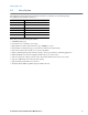
www.seagate.com 5.3 Supported ATA commands The following table lists SATA standard commands that the drive supports. For a detailed description of the ATA commands, refer to the Serial ATA International Organization: Serial ATA Revision 3.0 (http://www.sata-io.org). See “S.M.A.R.T. commands” on page 34 for details and subcommands used in the S.M.A.R.T. implementation.
www.seagate.com Command name Command code (in hex) Security Set Password F1H Security Unlock F2H Seek 70H Set Features EFH Set Max Address F9H Note: Individual Set Max Address commands are identified by the value placed in the Set Max Features register as defined to the right. Address: Password: Lock: Unlock: Freeze Lock: Set Max Address Extended 37H Set Multiple Mode C6H Sleep E6H S.M.A.R.T. Disable Operations B0H / D9H S.M.A.R.T. Enable/Disable Autosave B0H / D2H S.M.A.R.T.
www.seagate.com 5.3.1 Identify Device command The Identify Device command (command code ECH) transfers information about the drive to the host following power up. The data is organized as a single 512-byte block of data, whose contents are shown on page 28. All reserved bits or words should be set to zero. Parameters listed with an “x” are drive-specific or vary with the state of the drive. The following commands contain drive-specific features that may not be included in the SATA specification.
www.seagate.
www.seagate.com Bit Word 84 0 SMART error login is supported. 1 SMART self-test is supported. 2 Media serial number is supported. 3 Media Card Pass Through Command feature set is supported. 4 Streaming feature set is supported. 5 GPL feature set is supported. 6 WRITE DMA FUA EXT and WRITE MULTIPLE FUA EXT commands are supported. 7 WRITE DMA QUEUED FUA EXT command is supported. 8 64-bit World Wide Name is supported. 9-10 Obsolete. 11-12 Reserved for TLC.
www.seagate.com 5.3.2 Set Features command This command controls the implementation of various features that the drive supports. When the drive receives this command, it sets BSY, checks the contents of the Features register, clears BSY and generates an interrupt. If the value in the register does not represent a feature that the drive supports, the command is aborted. Power-on default has the read look-ahead and write caching features enabled.
www.seagate.com 5.3.3 S.M.A.R.T. commands S.M.A.R.T. provides near-term failure prediction for disk drives. When S.M.A.R.T. is enabled, the drive monitors predetermined drive attributes that are susceptible to degradation over time. If self-monitoring determines that a failure is likely, S.M.A.R.T. makes a status report available to the host. Not all failures are predictable. S.M.A.R.T. predictability is limited to the attributes the drive can monitor. For more information on S.M.A.R.T.
Index A ACA 20 acoustics 18 Active 13 Active mode 13 actuator arm 7 AES-256 25 Agency certification 19 altitude 17 ambient 16 Ambient temperature 16 ambient temperature 7 Annualized Failure Rate 19 Annualized Failure Rate (AFR) 19 areal density 6 ATA commands 28 Australia/New Zealand Standard AS/NZ CISPR22 20 Australian Communication Authority (ACA) 20 Australian C-Tick 20 average idle current 8 Average latency 7 Average seek time 7 B BPI 6 buffer 6 C cables and connectors 23 cache 6 capacity 5 CBC 25 CE ma
logical geometry 6 M maintenance 19 master/slave 3 maximum start current 8 mounting 24 mounting screws 17 mounting the drive 23 N noise 12 nominal power 7 non-operating temperature 16 Nonoperating shock 17 Nonoperating vibration 17 Nonrecoverable read errors 19 NOP 28 O Operating power 7 Operating shock 17 Operating vibration 17 P peak operating current 8 Physical characteristics 6 point-to-point 3, 23 Power consumption 7 power consumption 7 Power modes 13 Power specifications 7 Power-management modes 13 Po
Standby 13, 29 Standby Immediate 29 Standby mode 7, 13 standby timer 13 Standby to Ready 7 Start/stop times 7 static-discharge 23 subassembly 20 Surge immunity 18 T temperature 7, 16 non-operating 16 timer 13 timers 13 track density 6 Track-to-track 7 Track-to-track seek time 7 U UL60950-1 19 V Vibration 17 voltage 7 Voltage dips, interrupts 18 Voltage tolerance 12 W weight 6 Workload 19 Write Buffer 29 Write Buffer DMA 29 Write DMA 29 Write DMA Extended 29 Write DMA FUA Extended 29 Write Log DMA Ext 29 Wri
Seagate Technology LLC AMERICAS Seagate Technology LLC 10200 South De Anza Boulevard, Cupertino, California 95014, United States, 408-658-1000 ASIA/PACIFIC Seagate Singapore International Headquarters Pte. Ltd. 7000 Ang Mo Kio Avenue 5, Singapore 569877, 65-6485-3888 EUROPE, MIDDLE EAST AND AFRICA Seagate Technology SAS 16-18 rue du Dôme, 92100 Boulogne-Billancourt, France, 33 1-4186 10 00 Publication Number: 100695091, Rev.