Product Manual Constellation ES.2 Serial ATA ® Standard Model Self-Encrypting Drive Model ST33000650NS ST33000651NS SED FIPS 140-2 Model Review Pending ST33000652NS 100633157 Rev.
Revision history Revision Rev. A Rev. B Rev. C Rev. D Date 11/29/10 02/23/11 03/23/11 04/28/11 Sheets affected or comments Initial release. 2, 4-5, 7, 11, 15 & 23-24. 5, 7, 18, 21, 27-28 & 31. fc, 2, 4-5, 9 & 11. © 2011 Seagate Technology LLC. All rights reserved. Publication number: 100633157, Rev. D, April 2011 Seagate, Seagate Technology and the Wave logo are registered trademarks of Seagate Technology LLC in the United States and/or other countries.
Contents 1.0 Seagate Technology support services . . . . . . . . . . . . . . . . . . . . . . . . . . . . . . . . . . . . . . . . . . . . . 1 2.0 Introduction. . . . . . . . . . . . . . . . . . . . . . . . . . . . . . . . . . . . . . . . . . . . . . . . . . . . . . . . . . . . . . . . . . . 2 2.1 About the Serial ATA interface . . . . . . . . . . . . . . . . . . . . . . . . . . . . . . . . . . . . . . . . . . . . . . 3 3.0 Drive specifications . . . . . . . . . . . . . . . . . . . . . . . . . . . . . .
6.3 6.4 6.5 6.6 6.7 6.8 6.9 6.10 6.11 6.12 7.0 ii Random number generator (RNG). . . . . . . . . . . . . . . . . . . . . . . . . . . . . . . . . . . . . . . . . . . Drive locking. . . . . . . . . . . . . . . . . . . . . . . . . . . . . . . . . . . . . . . . . . . . . . . . . . . . . . . . . . . . Data bands. . . . . . . . . . . . . . . . . . . . . . . . . . . . . . . . . . . . . . . . . . . . . . . . . . . . . . . . . . . . . Cryptographic erase. . . . . . . . . . . . . . . . . . . . . . . . . . . . . . .
List of Figures Figure 1. Figure 2. Figure 3. Figure 4. Figure 5. Figure 6. Typical 5V startup and operation current profile . . . . . . . . . . . . . . . . . . . . . . . . . . . . . . . . . . . Typical 12V startup and operation current profile . . . . . . . . . . . . . . . . . . . . . . . . . . . . . . . . . . Location of the HDA temperature check point . . . . . . . . . . . . . . . . . . . . . . . . . . . . . . . . . . . . Attaching SATA cabling . . . . . . . . . . . . . . . . . . . . . . . . . . . . . .
1.0 Seagate Technology support services SEAGATE ONLINE SUPPORT and SERVICES For information regarding products and services, visit http://www.seagate.com/www/en-us/about/contact_us/ Available services include: Presales & Technical support Global Support Services telephone numbers & business hours Authorized Service Centers For information regarding Warranty Support, visit http://www.seagate.
2.0 Introduction This manual describes the functional, mechanical and interface specifications for the following Seagate Constellation® ES.2 Serial ATA model drives: Model Number Self-Encrypting Drive (SED) FIPS 140-2 Level 2 (Review Pending) ST33000652NS Yes Yes ST33000651NS Yes No ST33000650NS No No These drives provide the following key features: • 7200 RPM spindle speed.
2.1 About the Serial ATA interface The Serial ATA interface provides several advantages over the traditional (parallel) ATA interface. The primary advantages include: • Easy installation and configuration with true plug-and-play connectivity. It is not necessary to set any jumpers or other configuration options. • Thinner and more flexible cabling for improved enclosure airflow and ease of installation. • Scalability to higher performance levels.
3.0 Drive specifications Unless otherwise noted, all specifications are measured under ambient conditions, at 25°C, and nominal power. For convenience, the phrases the drive and this drive are used throughout this manual to indicate the following drive models: Model Number Self-Encrypting Drive (SED) FIPS 140-2 Level 2 (Review Pending) ST33000652NS Yes Yes ST33000651NS Yes No ST33000650NS No No 3.
Drive specification ST33000650NS ST33000651NS ST33000652NS Cache buffer 64MB Weight: (maximum) 700g (1.543 lb) Average latency 4.16ms Power-on to ready (sec max) 15 Standby to ready (sec max) 15 Track-to-track seek time (ms typical) 0.5 read 0.5 write Average seek, read (ms typical) 8.5 Average seek, write (ms typical) 9.5 Startup current (typical) 12V (peak) 2.8A 2.
3.2 Formatted capacity Model ST33000650NS ST33000651NS ST33000652NS Formatted capacity* Guaranteed sectors Bytes per sector 3TB 5,860,533,168 512 *One GB equals one billion bytes when referring to hard drive capacity. Accessible capacity may vary depending on operating environment and formatting. 3.2.1 LBA mode When addressing these drives in LBA mode, all blocks (sectors) are consecutively numbered from 0 to n–1, where n is the number of guaranteed sectors as defined above. See Section 7.3.
3.5 Physical characteristics Weight: (maximum) 700g (1.543 lb) Cache buffer 64MB (64,768KB) 3.6 Seek time Seek measurements are taken with nominal power at 25°C ambient temperature. All times are measured using drive diagnostics. The specifications in the table below are defined as follows: • Track-to-track seek time is an average of all possible single-track seeks in both directions.
3.8 Power specifications The drive receives DC power (+5V or +12V) through a native SATA power connector. See Figure 4 on page 23. 3.8.1 Power consumption Power requirements for the drives are listed in the table on page 9. Typical power measurements are based on an average of drives tested, under nominal conditions, using 5.0V and 12.0V input voltage at 25°C ambient temperature. • Spinup power Spinup power is measured from the time of power-on to the time that the drive spindle reaches operating speed.
Table 2: 3000GB Drive DC power requirements 3.0Gb mode Voltage +5V Regulation Avg Idle Current * +12V ± 5% 6.0Gb mode Power +5V (Watts) +12V ± 5% Power (Watts) 0.36 0.49 7.68 0.37 0.49 7.71 Idle_A 0.15 0.50 6.73 0.16 0.50 6.76 Idle_B 0.13 0.41 5.54 0.14 0.41 5.57 Idle_C 0.13 0.24 3.55 0.14 0.24 3.59 Standby 0.13 0.01 0.75 0.14 0.01 0.79 Idle_A (Active) 0.80 1.48 21.76 0.84 1.48 21.96 Idle_B (Active) 0.64 1.29 18.63 0.70 1.35 19.
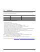
3.8.1.1 Typical current profiles Figure 1. Typical 5V startup and operation current profile 10 Constellation ES.2 Serial ATA Product Manual, Rev.
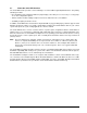
Figure 2. Typical 12V startup and operation current profile 3.8.2 Conducted noise Input noise ripple is measured at the host system power supply across an equivalent 80-ohm resistive load on the +12 V line or an equivalent 15-ohm resistive load on the +5V line. • Using 12V power, the drive is expected to operate with a maximum of 120mV peak-to-peak square-wave injected noise at up to 10MHz.
3.8.4 Power-management modes The drive provides programmable power management to provide greater energy efficiency. In most systems, you can control power management through the system setup program.
3.8.4.1 Extended Power Conditions - PowerChoiceTM Utilizing the load/unload architecture a programmable power management interface is provided to tailor systems for reduced power consumption and performance requirements. The table below lists the supported power conditions available in PowerChoice.
S.M.A.R.T. Read Data Reports • Attribute 192 - Emergency Retract Count • Attribute 193 - Load/Unload Cycle Count PowerChoice Manufacture Default Power Condition Timer Values Default power condition timer values have been established to assure product reliability and data integrity. A minimum timer value threshold of two minutes ensures the appropriate amount of background drive maintenance activities occur.
3.9 Environmental limits Temperature and humidity values experienced by the drive must be such that condensation does not occur on any drive part. Altitude and atmospheric pressure specifications are referenced to a standard day at 58.7°F (14.8°C). Maximum wet bulb temperature is 82°F (28°C). 3.9.1 Temperature a. Operating The drive meets the operating specifications over a 41°F to 140°F (5°C to 60°C) drive case temperature range with a maximum temperature gradient of 36°F (20°C) per hour.
3.9.2 Humidity 3.9.2.1 Relative humidity Operating: 5% to 90% noncondensing (30% per hour max) Nonoperating: 5% to 95% noncondensing (30% per hour max) 3.9.3 Altitude Operating: –60.96 m to 3,048 m (–200 ft. to 10,000+ ft.) Nonoperating: –60.96 m to 12,192 m (–200 ft. to 40,000+ ft.) 3.9.4 Shock All shock specifications assume that the drive is mounted securely with the input shock applied at the drive mounting screws. Shock may be applied in the X, Y or Z axis. 3.9.4.
3.10 Acoustics Drive acoustics are measured as overall A-weighted acoustic sound power levels (no pure tones). All measurements are consistent with ISO document 7779. Sound power measurements are taken under essentially free-field conditions over a reflecting plane. For all tests, the drive is oriented with the cover facing upward. Note. For seek mode tests, the drive is placed in seek mode only. The number of seeks per second is defined by the following equation: (Number of seeks per second = 0.
3.13 Reliability 3.13.1 Annualized Failure Rate (AFR) and Mean Time Between Failures (MTBF) The product shall achieve an Annualized Failure Rate (AFR) of 0.73% (MTBF of 1.2 million hours) when operated nominal power and typical case temperatures of 40°C. Operation at temperatures outside the specifications in Section 3.9 may increase the product AFR (decrease MTBF). AFR and MTBF are population statistics that are not relevant to individual units.
Korean RRL If these drives have the Korean Communications Commission (KCC) logo, they comply with paragraph 1 of Article 11 of the Electromagnetic Compatibility control Regulation and meet the Electromagnetic Compatibility (EMC) Framework requirements of the Radio Research Laboratory (RRL) Communications Commission, Republic of Korea. These drives have been tested and comply with the Electromagnetic Interference/Electromagnetic Susceptibility (EMI/EMS) for Class B products.
3.15 Environmental protection Seagate designs its products to meet environmental protection requirements worldwide, including regulations restricting certain chemical substances. 3.15.1 European Union Restriction of Hazardous Substances (RoHS) Directive Seagate designs its products to meet environmental protection requirements worldwide, including regulations restricting certain chemical substances.
3.17 Reference documents Self-Encrypting Drives Reference Manual Seagate part number: 100515636 Trusted Computing Group (TCG) Documents (apply to Self-Encrypting Drive models only) TCG Storage Architecture Core Specification, Rev. 1.0 TCG Storage Security Subsystem Class Enterprise Specification, Rev. 1.0 In case of conflict between this document and any referenced document, this document takes precedence. 3.
4.0 Configuring and mounting the drive This section contains the specifications and instructions for configuring and mounting the drive. 4.1 Handling and static-discharge precautions After unpacking, and before installation, the drive may be exposed to potential handling and electrostatic discharge (ESD) hazards.
4.2 Configuring the drive Each drive on the Serial ATA interface connects point-to-point with the Serial ATA host adapter. There is no master/slave relationship because each drive is considered a master in a point-to-point relationship. If two drives are attached on one Serial ATA host adapter, the host operating system views the two devices as if they were both “masters” on two separate ports. Both drives behave as if they are Device 0 (master) devices. 4.
4.4.1 Mechanical specifications Refer to Figure 5 for detailed mounting configuration dimensions. See Section 4.4, “Drive mounting.” Weight: Note. 1.543 lb 700 g These dimensions conform to the Small Form Factor Standard documented in SFF-8301 and SFF-8323, found at www.sffcommittee.org. in mm in mm Breather Hole in mm Figure 5. Mounting dimensions—top, side and end view 24 Constellation ES.2 Serial ATA Product Manual, Rev.
5.0 About FIPS The Federal Information Processing Standard (FIPS) Publication 140-2, FIPS PUB 140-2, is a U.S. government computer security standard used to accredit cryptographic modules. It is titled “Security Requirements for Cryptographic Modules”. The initial publication was on May 25, 2001 and was last updated December 3, 2002.
6.0 About self-encrypting drives Self-encrypting drives (SEDs) offer encryption and security services for the protection of stored data, commonly known as “protection of data at rest.” These drives are compliant with the Trusted Computing Group (TCG) Enterprise Storage Specifications as detailed in Section 3.17. The Trusted Computing Group (TCG) is an organization sponsored and operated by companies in the computer, storage and digital communications industry.
6.2.2 Locking SP The Locking SP controls read/write access to the media and the cryptographic erase feature. Access to the Locking SP is available using the BandMasterX or EraseMaster passwords. Since the drive owner can define up to 16 data bands on the drive, each data band has its own password called BandMasterX where X is the number of the data band (0 through 15). 6.2.3 Default password When the drive is shipped from the factory, all passwords are set to the value of MSID.
6.7 Authenticated firmware download In addition to providing a locking mechanism to prevent unwanted firmware download attempts, the drive also only accepts download files which have been cryptographically signed by the appropriate Seagate Design Center. Three conditions must be met before the drive will allow the download operation: 1. The download must be an SED file. A standard (base) drive (non-SED) file will be rejected. 2. The download file must be signed and authenticated. 3.
7.0 Serial ATA (SATA) interface These drives use the industry-standard Serial ATA interface that supports FIS data transfers. It supports ATA programmed input/output (PIO) modes 0–4; multiword DMA modes 0–2, and Ultra DMA modes 0–6. For detailed information about the Serial ATA interface, refer to the “Serial ATA: High Speed Serialized AT Attachment” specification. 7.1 Hot-Plug compatibility Constellation ES.
7.2 Serial ATA device plug connector pin definitions Table 5 summarizes the signals on the Serial ATA interface and power connectors. Table 5: Segment Signal Serial ATA connector pin definitions Pin Function Definition S1 Ground 2nd mate S2 A+ Differential signal pair A from Phy S3 A- S4 Ground 2nd mate S5 B- Differential signal pair B from Phy S6 B+ S7 Ground 2nd mate Key and spacing separate signal and power segments Power P1 V33 3.3V power P2 V33 3.3V power P3 V33 3.
7.3 Supported ATA commands The following table lists Serial ATA standard commands that the drive supports. For a detailed description of the ATA commands, refer to the Serial ATA: High Speed Serialized AT Attachment specification. See “S.M.A.R.T. commands” on page 38.for details and subcommands used in the S.M.A.R.T. implementation.
Command name Command code (in hex) Security Erase Prepare F3H Security Erase Unit F4H Security Freeze F5H Security Set Password F1H Security Unlock F2H Seek 70H Set Features EFH Set Max Address F9H Note: Individual Set Max Address commands are identified by the value placed in the Set Max Features register as defined to the right. Address: Password: Lock: Unlock: Freeze Lock: Set Max Address Extended 37H Set Multiple Mode C6H Sleep E6H S.M.A.R.T. Disable Operations B0H / D9H S.M.
7.3.1 Identify Device command The Identify Device command (command code ECH) transfers information about the drive to the host following power up. The data is organized as a single 512-byte block of data, whose contents are shown in Table 6 on page 31. All reserved bits or words should be set to zero. Parameters listed with an “x” are drive-specific or vary with the state of the drive. See Section 3.0 on page 4 for default parameter settings.
Word Description Value 60–61 Total number of user-addressable LBA sectors available (see Section 3.2 for related information) *Note: The maximum value allowed in this field is: 0FFFFFFFh (268,435,455 sectors, 137GB). Drives with capacities over 137GB will have 0FFFFFFFh in this field and the actual number of user-addressable LBAs specified in words 100-103. This is required for drives that support the 48-bit addressing feature.
Word Description Value 108–111 The mandatory value of the world wide name (WWN) for the drive. NOTE: This field is valid if word 84, bit 8 is set to 1 indicating 64-bit WWN support. Each drive will have a unique value. 112–127 ATA-reserved 0000H 128 Security status 0001H 129–159 Seagate-reserved xxxxH 160–254 ATA-reserved 0000H 255 Integrity word xxA5H Note. See the bit descriptions below for words 63, 84, and 88 of the Identify Drive data.
36 Bit Word 88 0 Ultra DMA mode 0 is supported. 1 Ultra DMA mode 1 is supported. 2 Ultra DMA mode 2 is supported. 3 Ultra DMA mode 3 is supported. 4 Ultra DMA mode 4 is supported. 5 Ultra DMA mode 5 is supported. 6 Ultra DMA mode 6 is supported. 8 Ultra DMA mode 0 is currently active. 9 Ultra DMA mode 1 is currently active. 10 Ultra DMA mode 2 is currently active. 11 Ultra DMA mode 3 is currently active. 12 Ultra DMA mode 4 is currently active.
7.3.2 Set Features command This command controls the implementation of various features that the drive supports. When the drive receives this command, it sets BSY, checks the contents of the Features register, clears BSY and generates an interrupt. If the value in the register does not represent a feature that the drive supports, the command is aborted. Power-on default has the read look-ahead and write caching features enabled.
7.3.3 S.M.A.R.T. commands S.M.A.R.T. provides near-term failure prediction for disc drives. When S.M.A.R.T. is enabled, the drive monitors predetermined drive attributes that are susceptible to degradation over time. If self-monitoring determines that a failure is likely, S.M.A.R.T. makes a status report available to the host. Not all failures are predictable. S.M.A.R.T. predictability is limited to the attributes the drive can monitor. For more information on S.M.A.R.T.
Index A ACA 19 acoustics 17 Active 12 Active mode 12 actuator arm 8 Admin SP 26 AES-128 data encryption 26 Agency certification 18 altitude 16 ambient 15 ambient temperature 7, 8 Annualized Failure Rate (AFR) 18 areal density 2, 6 ATA commands 31 Australia/New Zealand Standard AS/NZ CISPR22 19 Australian Communication Authority (ACA) 19 Australian C-Tick 19 average idle current 9 Average latency 7 Average seek time 7 B Band 0 27 BandMasterX 27 BPI 6 buffer 7 C cables and connectors 23 cache 7 capacity 6 C
Flush Cache 31 Flush Cache Extended 31 Format Track 31 Formatted capacity 6 G geometry 6 Global Data Band 27 gradient 15 guaranteed sectors 6 H Handling precautions 22 heads 6 humidity 16 humidity limits 15 I I/O data-transfer rate 6 Identify Device 31 Identify Device command 33 Idle 12, 31 Idle Immediate 31 Idle mode 8, 12 Information Technology Equipment (ITE) 18 Initialize Device Parameters 31 Input noise ripple 11 input voltage 8 interface 6, 29 interference 19 internal data-transfer rate OD 6 is 7 I
Read DMA 31 Read DMA Extended 31 Read DMA without Retries 31 read errors 18 Read Log Ext 31 Read Multiple 31 Read Multiple Extended 31 Read Native Max Address 31 Read Native Max Address Extended 31 Read Sectors 31 Read Sectors Extended 31 Read Sectors Without Retries 31 Read Verify Sectors 31 Read Verify Sectors Extended 31 Read Verify Sectors Without Retries 31 read/write actuator arm 8 Read/write heads 6 Read/write power 8 Recalibrate 31 recording density 6 recording method 6 Recording technology 6 refere
U UL60950-1 18 V Vibration 16 voltage 8 Voltage dips, interrupts 17 Voltage tolerance 11 W weight 7 wet bulb temperature 16 Write Buffer 32 Write DMA 32 Write DMA Extended 32 Write DMA FUA Extended 32 Write DMA Without Retries 32 Write Log Extended 32 Write Multiple 32 Write Multiple Extended 32 Write Multiple FUA Extended 32 Write Sectors 32 Write Sectors Extended 32 Write Sectors Without Retries 32 Write Uncorrectable 32 42 Constellation ES.2 Serial ATA Product Manual, Rev.
Seagate Technology LLC 920 Disc Drive, Scotts Valley, California 95066-4544, USA Publication Number: 100633157, Rev.