
Computer Drive User Manual
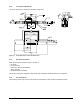
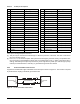
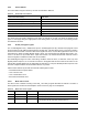
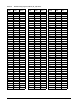
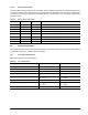
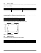

Table Of Contents
- 1.0 Scope 1
- 2.0 Standards, compliance and reference documents 3
- 3.0 General description 7
- 4.0 Performance characteristics 11
- 5.0 Reliability specifications 15
- 6.0 Physical/electrical specifications 23
- 6.1 AC power requirements 23
- 6.2 DC power requirements 23
- 6.3 Power dissipation 29
- 6.4 Environmental limits 32
- 6.4.1 Temperature 32
- 6.4.2 Relative humidity 32
- 6.4.3 Effective altitude (sea level) 33
- 6.4.4 Shock and vibration 33
- 6.4.5 Acoustics 35
- 6.4.6 Air cleanliness 35
- 6.4.7 Corrosive environment 35
- 6.4.8 European Union Restriction of Hazardous Substances (RoHS) Directive 36
- 6.4.9 China Restriction of Hazardous Substances (RoHS) Directive 36
- 6.4.10 Electromagnetic susceptibility 36
- 6.5 Mechanical specifications 37
- 7.0 Defect and error management 39
- 8.0 Installation 43
- 9.0 Interface requirements 47
- 9.1 FC-AL features 47
- 9.1.1 Fibre Channel link service frames 47
- 9.1.2 Fibre Channel task management functions 48
- 9.1.3 Fibre Channel task management responses 48
- 9.1.4 Fibre Channel port login 49
- 9.1.5 Fibre Channel port login accept 50
- 9.1.6 Fibre Channel Process Login 50
- 9.1.7 Fibre Channel Process Login Accept 51
- 9.1.8 Fibre Channel fabric login 51
- 9.1.9 Fibre Channel fabric accept login 52
- 9.1.10 Fibre Channel Arbitrated Loop options 53
- 9.2 Dual port support 53
- 9.3 SCSI commands supported 54
- 9.4 Miscellaneous operating features and conditions 63
- 9.5 FC-AL physical interface 64
- 9.5.1 Physical characteristics 64
- 9.5.2 Connector requirements 65
- 9.5.3 Electrical description 65
- 9.5.4 Pin descriptions 65
- 9.5.5 FC-AL transmitters and receivers 66
- 9.5.6 Power 67
- 9.5.7 Fault LED Out 67
- 9.5.8 Active LED Out 68
- 9.5.9 Enable port bypass signals 68
- 9.5.10 Motor start controls 68
- 9.5.11 SEL_6 through SEL_0 ID lines 69
- 9.5.12 Device control codes 71
- 9.6 Signal characteristics 71
- 9.1 FC-AL features 47
- 10.0 Seagate Technology support services 75
- 1.0 Scope
- 2.0 Standards, compliance and reference documents
- 3.0 General description
- 4.0 Performance characteristics
- 5.0 Reliability specifications
- 6.0 Physical/electrical specifications
- 6.1 AC power requirements
- 6.2 DC power requirements
- 6.3 Power dissipation
- 6.4 Environmental limits
- 6.4.1 Temperature
- 6.4.2 Relative humidity
- 6.4.3 Effective altitude (sea level)
- 6.4.4 Shock and vibration
- 6.4.5 Acoustics
- 6.4.6 Air cleanliness
- 6.4.7 Corrosive environment
- 6.4.8 European Union Restriction of Hazardous Substances (RoHS) Directive
- 6.4.9 China Restriction of Hazardous Substances (RoHS) Directive
- 6.4.10 Electromagnetic susceptibility
- 6.5 Mechanical specifications
- 7.0 Defect and error management
- 8.0 Installation
- 9.0 Interface requirements
- 9.1 FC-AL features
- 9.1.1 Fibre Channel link service frames
- 9.1.2 Fibre Channel task management functions
- 9.1.3 Fibre Channel task management responses
- 9.1.4 Fibre Channel port login
- 9.1.5 Fibre Channel port login accept
- 9.1.6 Fibre Channel Process Login
- 9.1.7 Fibre Channel Process Login Accept
- 9.1.8 Fibre Channel fabric login
- 9.1.9 Fibre Channel fabric accept login
- 9.1.10 Fibre Channel Arbitrated Loop options
- 9.2 Dual port support
- 9.3 SCSI commands supported
- 9.4 Miscellaneous operating features and conditions
- 9.5 FC-AL physical interface
- 9.5.1 Physical characteristics
- 9.5.2 Connector requirements
- 9.5.3 Electrical description
- 9.5.4 Pin descriptions
- 9.5.5 FC-AL transmitters and receivers
- 9.5.6 Power
- 9.5.7 Fault LED Out
- 9.5.8 Active LED Out
- 9.5.9 Enable port bypass signals
- 9.5.10 Motor start controls
- 9.5.11 SEL_6 through SEL_0 ID lines
- 9.5.12 Device control codes
- 9.6 Signal characteristics
- 9.1 FC-AL features
- 10.0 Seagate Technology support services

Cheetah NS 10K.2 FC Product Manual, Rev. B 69
9.5.11 SEL_6 through SEL_0 ID lines
The SEL_6 through SEL_0 ID lines determine drive address, and, optionally, for an Enclosure Services Inter-
face. When the Parallel ESI line is high, the enclosure backpanel must provide address information on the SEL
line. Refer to table 26 for a mapping of SEL to FC-AL physical addresses (AL_PA). You can think of the SEL
lines as the equivalent of a backpanel logic plug. The drives does not provide pull up resistors on these lines.
The backpanel is required to provide high and low inputs to the SEL_ID lines per the specifications in table 28
on page 71.
Note. Tab l e 26 gives AL_PA values for each SEL value. The first entry in the table is SEL_ID 00. The last
entry is SEL_ID 7D. SEL_ID 7E is AL_PA 00 which is not valid for an NL_Port, so is not included in
the table. Also, SEL_ID 7Fh does map to a valid AL_PA; however, this value signals the drive that
physical addresses are not being assigned using the SEL lines and that a “soft” address will be
determined by FC-AL loop initialization.
When the Parallel ESI line is low, the enclosure backpanel logic switches to ESI mode if supported. There are
two modes of ESI, seven bits of enclosure status and a bidirectional mode. ESI support and the mode are
determined by the drive using a discovery process. Refer to the Fibre Channel Interface Manual for a descrip-
tion of ESI operation.
9.5.11.1 Parallel Enclosure Services Interface (ESI)
The parallel ESI line is an output from the drive. This line provides the enclosure with an indication of the pres-
ent function of the SEL lines. A high level, the default state, indicates the drive requires address information on
the SEL lines. A low level indicates the drive is attempting an ESI transfer. The enclosure may not support ESI
on any or all drive locations. It may only support the address function. Support of ESI is discovered by the
drive. Refer to the Fibre Channel Interface Manual for a description of ESI operations.
4 High High The drive will not spin up.
Table 25: Motor start control signals
Case Start_2 Start_1 Motor spin function