
Computer Drive User Manual
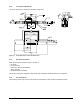
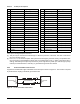
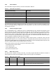
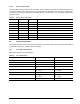
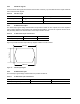

Table Of Contents
- 1.0 Scope 1
- 2.0 Standards, compliance and reference documents 3
- 3.0 General description 7
- 4.0 Performance characteristics 11
- 5.0 Reliability specifications 15
- 6.0 Physical/electrical specifications 23
- 6.1 AC power requirements 23
- 6.2 DC power requirements 23
- 6.3 Power dissipation 29
- 6.4 Environmental limits 32
- 6.4.1 Temperature 32
- 6.4.2 Relative humidity 32
- 6.4.3 Effective altitude (sea level) 33
- 6.4.4 Shock and vibration 33
- 6.4.5 Acoustics 35
- 6.4.6 Air cleanliness 35
- 6.4.7 Corrosive environment 35
- 6.4.8 European Union Restriction of Hazardous Substances (RoHS) Directive 36
- 6.4.9 China Restriction of Hazardous Substances (RoHS) Directive 36
- 6.4.10 Electromagnetic susceptibility 36
- 6.5 Mechanical specifications 37
- 7.0 Defect and error management 39
- 8.0 Installation 43
- 9.0 Interface requirements 47
- 9.1 FC-AL features 47
- 9.1.1 Fibre Channel link service frames 47
- 9.1.2 Fibre Channel task management functions 48
- 9.1.3 Fibre Channel task management responses 48
- 9.1.4 Fibre Channel port login 49
- 9.1.5 Fibre Channel port login accept 50
- 9.1.6 Fibre Channel Process Login 50
- 9.1.7 Fibre Channel Process Login Accept 51
- 9.1.8 Fibre Channel fabric login 51
- 9.1.9 Fibre Channel fabric accept login 52
- 9.1.10 Fibre Channel Arbitrated Loop options 53
- 9.2 Dual port support 53
- 9.3 SCSI commands supported 54
- 9.4 Miscellaneous operating features and conditions 63
- 9.5 FC-AL physical interface 64
- 9.5.1 Physical characteristics 64
- 9.5.2 Connector requirements 65
- 9.5.3 Electrical description 65
- 9.5.4 Pin descriptions 65
- 9.5.5 FC-AL transmitters and receivers 66
- 9.5.6 Power 67
- 9.5.7 Fault LED Out 67
- 9.5.8 Active LED Out 68
- 9.5.9 Enable port bypass signals 68
- 9.5.10 Motor start controls 68
- 9.5.11 SEL_6 through SEL_0 ID lines 69
- 9.5.12 Device control codes 71
- 9.6 Signal characteristics 71
- 9.1 FC-AL features 47
- 10.0 Seagate Technology support services 75
- 1.0 Scope
- 2.0 Standards, compliance and reference documents
- 3.0 General description
- 4.0 Performance characteristics
- 5.0 Reliability specifications
- 6.0 Physical/electrical specifications
- 6.1 AC power requirements
- 6.2 DC power requirements
- 6.3 Power dissipation
- 6.4 Environmental limits
- 6.4.1 Temperature
- 6.4.2 Relative humidity
- 6.4.3 Effective altitude (sea level)
- 6.4.4 Shock and vibration
- 6.4.5 Acoustics
- 6.4.6 Air cleanliness
- 6.4.7 Corrosive environment
- 6.4.8 European Union Restriction of Hazardous Substances (RoHS) Directive
- 6.4.9 China Restriction of Hazardous Substances (RoHS) Directive
- 6.4.10 Electromagnetic susceptibility
- 6.5 Mechanical specifications
- 7.0 Defect and error management
- 8.0 Installation
- 9.0 Interface requirements
- 9.1 FC-AL features
- 9.1.1 Fibre Channel link service frames
- 9.1.2 Fibre Channel task management functions
- 9.1.3 Fibre Channel task management responses
- 9.1.4 Fibre Channel port login
- 9.1.5 Fibre Channel port login accept
- 9.1.6 Fibre Channel Process Login
- 9.1.7 Fibre Channel Process Login Accept
- 9.1.8 Fibre Channel fabric login
- 9.1.9 Fibre Channel fabric accept login
- 9.1.10 Fibre Channel Arbitrated Loop options
- 9.2 Dual port support
- 9.3 SCSI commands supported
- 9.4 Miscellaneous operating features and conditions
- 9.5 FC-AL physical interface
- 9.5.1 Physical characteristics
- 9.5.2 Connector requirements
- 9.5.3 Electrical description
- 9.5.4 Pin descriptions
- 9.5.5 FC-AL transmitters and receivers
- 9.5.6 Power
- 9.5.7 Fault LED Out
- 9.5.8 Active LED Out
- 9.5.9 Enable port bypass signals
- 9.5.10 Motor start controls
- 9.5.11 SEL_6 through SEL_0 ID lines
- 9.5.12 Device control codes
- 9.6 Signal characteristics
- 9.1 FC-AL features
- 10.0 Seagate Technology support services

68 Cheetah NS 10K.2 FC Product Manual, Rev. B
9.5.8 Active LED Out
The Active LED Out signal is driven by the drive as indicated in Table 24.
The Active LED Out signal is designed to pull down the cathode of an LED. The anode is attached to the
proper +5 volt supply through an appropriate current limiting resistor. The LED and the current limiting resistor
are external to the drive.
9.5.9 Enable port bypass signals
The – Enable Bypass Port A (– EN BYP Port A) and – Enable Bypass Port B (– EN BYP Port B) signals control
the port bypass circuits (PBC) located external to the disk drive. The PBC allows a loop to remain functional in
the event of a drive failure or removal. When these signals are active, low, the PBC bypasses the drive on the
associated port. When an Enable Bypass signal is active, the corresponding Port Bypass LED signal in con-
nector J1 is driven low by the disk drive. A pull down resistor, 1K, located with the PBC should be used to
insure the bypass is enabled if the disk drive is not installed.
The Enable Bypass signal is active under failing conditions within the drive, on detection of the Loop Port
Bypass primitive sequence, or on removal of the drive. In the bypass state the drive continues to receive on the
inbound fibre. Enable Bypass may be deactivated by detection of a Loop Port Enable primitive sequence if the
drive has completed self-test and a hardware failure is not present.
Failure modes detected by the disk drive that will enable bypass include:
• Transmitter/receiver wrap test failure
• Loss of receive clock
• Loss of transmission clock
• Drive interface hardware error
9.5.10 Motor start controls
The drive’s motor is started according to the Start_1 and Start_2 signals described in Table 25. The state of
these signals can be wired into the backplane socket or driven by logic on the backplane.
Table 24: Active LED Out conditions
Normal command activity LED status
Spun down and no activity Slow blink (20% on and 80% off a 2 sec cycle)
Spun down and activity (command executing) On
Spun up and no activity On
Spun up and activity (command executing) Off
Spinning up or down Blinks steadily (50% on and 50% off)
Format in progress Toggles on/off
Write Same command in progress Togles on/off
Table 25: Motor start control signals
Case Start_2 Start_1 Motor spin function
1 Low Low Motor spins up at DC power on.
2 High Low Motor spins up only when SCSI Start command is received.
3 Low High Motor spins up after a delay of 12 seconds times the modulo 8 value
of the numeric SEL ID of the drive from DC power on.