
Computer Drive User Manual
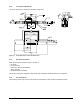
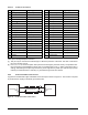
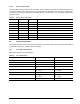
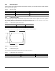
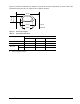

Table Of Contents
- 1.0 Scope 1
- 2.0 Standards, compliance and reference documents 3
- 3.0 General description 7
- 4.0 Performance characteristics 11
- 5.0 Reliability specifications 15
- 6.0 Physical/electrical specifications 23
- 6.1 AC power requirements 23
- 6.2 DC power requirements 23
- 6.3 Power dissipation 29
- 6.4 Environmental limits 32
- 6.4.1 Temperature 32
- 6.4.2 Relative humidity 32
- 6.4.3 Effective altitude (sea level) 33
- 6.4.4 Shock and vibration 33
- 6.4.5 Acoustics 35
- 6.4.6 Air cleanliness 35
- 6.4.7 Corrosive environment 35
- 6.4.8 European Union Restriction of Hazardous Substances (RoHS) Directive 36
- 6.4.9 China Restriction of Hazardous Substances (RoHS) Directive 36
- 6.4.10 Electromagnetic susceptibility 36
- 6.5 Mechanical specifications 37
- 7.0 Defect and error management 39
- 8.0 Installation 43
- 9.0 Interface requirements 47
- 9.1 FC-AL features 47
- 9.1.1 Fibre Channel link service frames 47
- 9.1.2 Fibre Channel task management functions 48
- 9.1.3 Fibre Channel task management responses 48
- 9.1.4 Fibre Channel port login 49
- 9.1.5 Fibre Channel port login accept 50
- 9.1.6 Fibre Channel Process Login 50
- 9.1.7 Fibre Channel Process Login Accept 51
- 9.1.8 Fibre Channel fabric login 51
- 9.1.9 Fibre Channel fabric accept login 52
- 9.1.10 Fibre Channel Arbitrated Loop options 53
- 9.2 Dual port support 53
- 9.3 SCSI commands supported 54
- 9.4 Miscellaneous operating features and conditions 63
- 9.5 FC-AL physical interface 64
- 9.5.1 Physical characteristics 64
- 9.5.2 Connector requirements 65
- 9.5.3 Electrical description 65
- 9.5.4 Pin descriptions 65
- 9.5.5 FC-AL transmitters and receivers 66
- 9.5.6 Power 67
- 9.5.7 Fault LED Out 67
- 9.5.8 Active LED Out 68
- 9.5.9 Enable port bypass signals 68
- 9.5.10 Motor start controls 68
- 9.5.11 SEL_6 through SEL_0 ID lines 69
- 9.5.12 Device control codes 71
- 9.6 Signal characteristics 71
- 9.1 FC-AL features 47
- 10.0 Seagate Technology support services 75
- 1.0 Scope
- 2.0 Standards, compliance and reference documents
- 3.0 General description
- 4.0 Performance characteristics
- 5.0 Reliability specifications
- 6.0 Physical/electrical specifications
- 6.1 AC power requirements
- 6.2 DC power requirements
- 6.3 Power dissipation
- 6.4 Environmental limits
- 6.4.1 Temperature
- 6.4.2 Relative humidity
- 6.4.3 Effective altitude (sea level)
- 6.4.4 Shock and vibration
- 6.4.5 Acoustics
- 6.4.6 Air cleanliness
- 6.4.7 Corrosive environment
- 6.4.8 European Union Restriction of Hazardous Substances (RoHS) Directive
- 6.4.9 China Restriction of Hazardous Substances (RoHS) Directive
- 6.4.10 Electromagnetic susceptibility
- 6.5 Mechanical specifications
- 7.0 Defect and error management
- 8.0 Installation
- 9.0 Interface requirements
- 9.1 FC-AL features
- 9.1.1 Fibre Channel link service frames
- 9.1.2 Fibre Channel task management functions
- 9.1.3 Fibre Channel task management responses
- 9.1.4 Fibre Channel port login
- 9.1.5 Fibre Channel port login accept
- 9.1.6 Fibre Channel Process Login
- 9.1.7 Fibre Channel Process Login Accept
- 9.1.8 Fibre Channel fabric login
- 9.1.9 Fibre Channel fabric accept login
- 9.1.10 Fibre Channel Arbitrated Loop options
- 9.2 Dual port support
- 9.3 SCSI commands supported
- 9.4 Miscellaneous operating features and conditions
- 9.5 FC-AL physical interface
- 9.5.1 Physical characteristics
- 9.5.2 Connector requirements
- 9.5.3 Electrical description
- 9.5.4 Pin descriptions
- 9.5.5 FC-AL transmitters and receivers
- 9.5.6 Power
- 9.5.7 Fault LED Out
- 9.5.8 Active LED Out
- 9.5.9 Enable port bypass signals
- 9.5.10 Motor start controls
- 9.5.11 SEL_6 through SEL_0 ID lines
- 9.5.12 Device control codes
- 9.6 Signal characteristics
- 9.1 FC-AL features
- 10.0 Seagate Technology support services
66 Cheetah NS 10K.2 FC Product Manual, Rev. B
Table 23: FC-SCA pin descriptions
Pin Signal name Signal type Pin Signal name
Signal type
1* -EN bypass port A Low Voltage TTL output 21 12 Volts charge
2* 12 Volts 22 Ground
3* 12 Volts 23 Ground
4* 12 Volts 24* +Port A_in FC Diff. input pair
5* -Parallel ESI 25* -Port A_in
6* Ground
[1]
26 Ground
7* Active LED out Open collector out 27* +Port B_in FC Diff. input pair
8* Reserved 28* -Port B_in
9* Start_1
[2]
TTL input 29 Ground
10* Start_2
[2]
TTL input 30* +Port A_out FC Diff. output pair
11* -EN bypass port B Low Voltage TTL output 31* -Port A_out
12* SEL_6 TTL input/output 32 Ground
13* SEL_5 TTL input/output 33* +Port B_out FC Diff. output pair
14* SEL_4 TTL input 34* -Port B_out
15* SEL_3 TTL input/output 35 Ground
16* Fault LED out Open collector out 36 SEL_2 TTL input/output
17* DEV_CTRL_CODE_2
[2]
TTL input 37 SEL_1 TTL input/output
18* DEV_CTRL_CODE_1
[2]
TTL input 38 SEL_0 TTL input/output
19* 5 Volts 39 DEV_CTRL_CODE_0
[2
TTL input
20* 5 Volts 40 5 Volts charge
*Short pins in mating backpanel connector.
[1] This pin may be connected to external logic to detect the
presence of the drive. The drive connects this
pin to the common ground.
[2] Pins 9, 10, 17, 18, and 39 are option select pins and are tie
d high by the drive circuitry. The preferred elec-
trical connection at the backplane is either open or grounded (open for the ‘1’ setting, grounded for the ‘0’
setting)
. Alternatively, these pins may be driven by a 3.3V logic device, pulled up to 3.3V through a pull-up
resistor (recommended size of 10k ohm), or grounded through some other means.
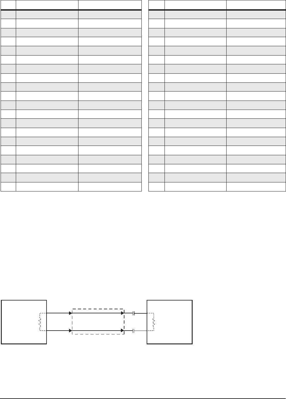
9.5.5 FC-AL transmitters and receivers
A typical FC-AL differential copper transmitter and receiver p
air is shown in Figure 14. The receiver is required
to provide the AC coupling to eliminate ground shift noise.
Figure 14. FC-AL transmitters and receivers
TY
.01
Differential
Transfer Medium
.01
Transmitter
TX
RY
Receiver
RX
100
100