
Computer Drive User Manual

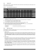
Table Of Contents
- 1.0 Scope 1
- 2.0 Standards, compliance and reference documents 3
- 3.0 General description 7
- 4.0 Performance characteristics 11
- 5.0 Reliability specifications 15
- 6.0 Physical/electrical specifications 23
- 6.1 AC power requirements 23
- 6.2 DC power requirements 23
- 6.3 Power dissipation 29
- 6.4 Environmental limits 32
- 6.4.1 Temperature 32
- 6.4.2 Relative humidity 32
- 6.4.3 Effective altitude (sea level) 33
- 6.4.4 Shock and vibration 33
- 6.4.5 Acoustics 35
- 6.4.6 Air cleanliness 35
- 6.4.7 Corrosive environment 35
- 6.4.8 European Union Restriction of Hazardous Substances (RoHS) Directive 36
- 6.4.9 China Restriction of Hazardous Substances (RoHS) Directive 36
- 6.4.10 Electromagnetic susceptibility 36
- 6.5 Mechanical specifications 37
- 7.0 Defect and error management 39
- 8.0 Installation 43
- 9.0 Interface requirements 47
- 9.1 FC-AL features 47
- 9.1.1 Fibre Channel link service frames 47
- 9.1.2 Fibre Channel task management functions 48
- 9.1.3 Fibre Channel task management responses 48
- 9.1.4 Fibre Channel port login 49
- 9.1.5 Fibre Channel port login accept 50
- 9.1.6 Fibre Channel Process Login 50
- 9.1.7 Fibre Channel Process Login Accept 51
- 9.1.8 Fibre Channel fabric login 51
- 9.1.9 Fibre Channel fabric accept login 52
- 9.1.10 Fibre Channel Arbitrated Loop options 53
- 9.2 Dual port support 53
- 9.3 SCSI commands supported 54
- 9.4 Miscellaneous operating features and conditions 63
- 9.5 FC-AL physical interface 64
- 9.5.1 Physical characteristics 64
- 9.5.2 Connector requirements 65
- 9.5.3 Electrical description 65
- 9.5.4 Pin descriptions 65
- 9.5.5 FC-AL transmitters and receivers 66
- 9.5.6 Power 67
- 9.5.7 Fault LED Out 67
- 9.5.8 Active LED Out 68
- 9.5.9 Enable port bypass signals 68
- 9.5.10 Motor start controls 68
- 9.5.11 SEL_6 through SEL_0 ID lines 69
- 9.5.12 Device control codes 71
- 9.6 Signal characteristics 71
- 9.1 FC-AL features 47
- 10.0 Seagate Technology support services 75
- 1.0 Scope
- 2.0 Standards, compliance and reference documents
- 3.0 General description
- 4.0 Performance characteristics
- 5.0 Reliability specifications
- 6.0 Physical/electrical specifications
- 6.1 AC power requirements
- 6.2 DC power requirements
- 6.3 Power dissipation
- 6.4 Environmental limits
- 6.4.1 Temperature
- 6.4.2 Relative humidity
- 6.4.3 Effective altitude (sea level)
- 6.4.4 Shock and vibration
- 6.4.5 Acoustics
- 6.4.6 Air cleanliness
- 6.4.7 Corrosive environment
- 6.4.8 European Union Restriction of Hazardous Substances (RoHS) Directive
- 6.4.9 China Restriction of Hazardous Substances (RoHS) Directive
- 6.4.10 Electromagnetic susceptibility
- 6.5 Mechanical specifications
- 7.0 Defect and error management
- 8.0 Installation
- 9.0 Interface requirements
- 9.1 FC-AL features
- 9.1.1 Fibre Channel link service frames
- 9.1.2 Fibre Channel task management functions
- 9.1.3 Fibre Channel task management responses
- 9.1.4 Fibre Channel port login
- 9.1.5 Fibre Channel port login accept
- 9.1.6 Fibre Channel Process Login
- 9.1.7 Fibre Channel Process Login Accept
- 9.1.8 Fibre Channel fabric login
- 9.1.9 Fibre Channel fabric accept login
- 9.1.10 Fibre Channel Arbitrated Loop options
- 9.2 Dual port support
- 9.3 SCSI commands supported
- 9.4 Miscellaneous operating features and conditions
- 9.5 FC-AL physical interface
- 9.5.1 Physical characteristics
- 9.5.2 Connector requirements
- 9.5.3 Electrical description
- 9.5.4 Pin descriptions
- 9.5.5 FC-AL transmitters and receivers
- 9.5.6 Power
- 9.5.7 Fault LED Out
- 9.5.8 Active LED Out
- 9.5.9 Enable port bypass signals
- 9.5.10 Motor start controls
- 9.5.11 SEL_6 through SEL_0 ID lines
- 9.5.12 Device control codes
- 9.6 Signal characteristics
- 9.1 FC-AL features
- 10.0 Seagate Technology support services

Cheetah NS 10K.2 FC Product Manual, Rev. B 59
On standard OEM drives, the saved values are taken from the default values list and stored into the saved
values storage location on the media prior to shipping.
3. Current values
Current values are volatile values being used by the drive to control its operation. A Mode Select command
can be used to change the values identified as changeable values. Originally, current values are installed
from saved or default values after a power on reset, hard reset, or Bus Device Reset message.
4. Changeable values
Changeable values form a bit mask, stored in nonvolatile memory, that dictates which of the current values
and saved values can be changed by a Mode Select command. A one (1) indicates the value can be
changed. A zero (0) indicates the value is not changeable. For example, in Table
18, refer to Mode page
81, in the row entitled “CHG.” These are hex numbers representing the changeable values for Mode page
81. Note in columns 5 and 6 (bytes 04 and 05), there is 00h which indicates that in bytes 04 and 05 none of
the bits are changeable. Note also that bytes 06, 07, 09, 10, and 11 are not changeable, because those
fields are all zeros. In byte 02, hex value FF equates to the binary pattern 11111111. If there is a zero in any
bit position in the field, it means that bit is not changeable. Since all of the bits in byte 02 are ones, all of
these bits are changeable.
The changeable values list can only be changed by downloading new firmware into the flash E-PROM.
Note. Because there are often several different versions of drive control firmware in the total population of
drives in the field, the Mode Sense values given in the following tables may not exactly match those
of some drives.
The following tables list the values of the data bytes returned by the drive in response to the Mode Sense com-
mand pages for SCSI implementation (see the Fibre Channel Interface Manual ).
Definitions:
DEF = Default value. Standard OEM drives are shipped configured this way.
CHG = Changeable bits; indicates if default value is changeable.