
Computer Drive User Manual

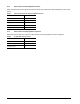
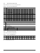
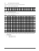
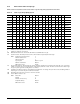

Table Of Contents
- 1.0 Scope 1
- 2.0 Standards, compliance and reference documents 3
- 3.0 General description 7
- 4.0 Performance characteristics 11
- 5.0 Reliability specifications 15
- 6.0 Physical/electrical specifications 23
- 6.1 AC power requirements 23
- 6.2 DC power requirements 23
- 6.3 Power dissipation 29
- 6.4 Environmental limits 32
- 6.4.1 Temperature 32
- 6.4.2 Relative humidity 32
- 6.4.3 Effective altitude (sea level) 33
- 6.4.4 Shock and vibration 33
- 6.4.5 Acoustics 35
- 6.4.6 Air cleanliness 35
- 6.4.7 Corrosive environment 35
- 6.4.8 European Union Restriction of Hazardous Substances (RoHS) Directive 36
- 6.4.9 China Restriction of Hazardous Substances (RoHS) Directive 36
- 6.4.10 Electromagnetic susceptibility 36
- 6.5 Mechanical specifications 37
- 7.0 Defect and error management 39
- 8.0 Installation 43
- 9.0 Interface requirements 47
- 9.1 FC-AL features 47
- 9.1.1 Fibre Channel link service frames 47
- 9.1.2 Fibre Channel task management functions 48
- 9.1.3 Fibre Channel task management responses 48
- 9.1.4 Fibre Channel port login 49
- 9.1.5 Fibre Channel port login accept 50
- 9.1.6 Fibre Channel Process Login 50
- 9.1.7 Fibre Channel Process Login Accept 51
- 9.1.8 Fibre Channel fabric login 51
- 9.1.9 Fibre Channel fabric accept login 52
- 9.1.10 Fibre Channel Arbitrated Loop options 53
- 9.2 Dual port support 53
- 9.3 SCSI commands supported 54
- 9.4 Miscellaneous operating features and conditions 63
- 9.5 FC-AL physical interface 64
- 9.5.1 Physical characteristics 64
- 9.5.2 Connector requirements 65
- 9.5.3 Electrical description 65
- 9.5.4 Pin descriptions 65
- 9.5.5 FC-AL transmitters and receivers 66
- 9.5.6 Power 67
- 9.5.7 Fault LED Out 67
- 9.5.8 Active LED Out 68
- 9.5.9 Enable port bypass signals 68
- 9.5.10 Motor start controls 68
- 9.5.11 SEL_6 through SEL_0 ID lines 69
- 9.5.12 Device control codes 71
- 9.6 Signal characteristics 71
- 9.1 FC-AL features 47
- 10.0 Seagate Technology support services 75
- 1.0 Scope
- 2.0 Standards, compliance and reference documents
- 3.0 General description
- 4.0 Performance characteristics
- 5.0 Reliability specifications
- 6.0 Physical/electrical specifications
- 6.1 AC power requirements
- 6.2 DC power requirements
- 6.3 Power dissipation
- 6.4 Environmental limits
- 6.4.1 Temperature
- 6.4.2 Relative humidity
- 6.4.3 Effective altitude (sea level)
- 6.4.4 Shock and vibration
- 6.4.5 Acoustics
- 6.4.6 Air cleanliness
- 6.4.7 Corrosive environment
- 6.4.8 European Union Restriction of Hazardous Substances (RoHS) Directive
- 6.4.9 China Restriction of Hazardous Substances (RoHS) Directive
- 6.4.10 Electromagnetic susceptibility
- 6.5 Mechanical specifications
- 7.0 Defect and error management
- 8.0 Installation
- 9.0 Interface requirements
- 9.1 FC-AL features
- 9.1.1 Fibre Channel link service frames
- 9.1.2 Fibre Channel task management functions
- 9.1.3 Fibre Channel task management responses
- 9.1.4 Fibre Channel port login
- 9.1.5 Fibre Channel port login accept
- 9.1.6 Fibre Channel Process Login
- 9.1.7 Fibre Channel Process Login Accept
- 9.1.8 Fibre Channel fabric login
- 9.1.9 Fibre Channel fabric accept login
- 9.1.10 Fibre Channel Arbitrated Loop options
- 9.2 Dual port support
- 9.3 SCSI commands supported
- 9.4 Miscellaneous operating features and conditions
- 9.5 FC-AL physical interface
- 9.5.1 Physical characteristics
- 9.5.2 Connector requirements
- 9.5.3 Electrical description
- 9.5.4 Pin descriptions
- 9.5.5 FC-AL transmitters and receivers
- 9.5.6 Power
- 9.5.7 Fault LED Out
- 9.5.8 Active LED Out
- 9.5.9 Enable port bypass signals
- 9.5.10 Motor start controls
- 9.5.11 SEL_6 through SEL_0 ID lines
- 9.5.12 Device control codes
- 9.6 Signal characteristics
- 9.1 FC-AL features
- 10.0 Seagate Technology support services
Cheetah NS 10K.2 FC Product Manual, Rev. B 49
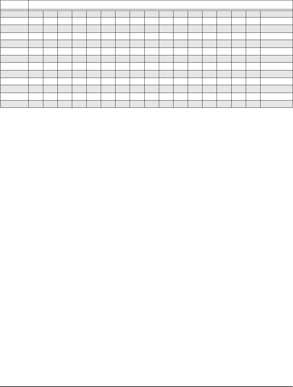
9.1.4 Fibre Channel port login
Table 9 identifies the required content of the N_Port Login (PLOGI) payload from an initiator.
Table 9: N_Port login (PLOGI) payload
Bytes
0-15 03 00 00 00 09 09 BB BB CF XX FS FS XX XX XX XX Common
16-31 XX XX XX XX PN PN PN PN PN PN PN PN NN NN NN NN
32-35 NN NN NN NN
36-47 XX XX XX XX XX XX XX XX XX XX XX XX Class 1
48-51 XX XX XX XX
52-63 XX XX XX XX XX XX XX XX XX XX XX XX Class 2
64-67 XX XX XX XX
68-79 SO SO IC IC XX XX FS FS XX CS XX XX Class 3
80-83 OS OS XX XX
84-95 XX XX XX XX XX XX XX XX XX XX XX XX Reserved
96-99 XX XX XX XX
100-111 XX XX XX XX XX XX XX XX XX XX XX XX Vendor
112-115 XX XX XX XX Version
X Indicates a four-bit (hex) field is not checked.
x Indicates a single bit is not checked.
BB BB-Credit. This field is not checked. The FC-AL drive uses BB-Credit of zero (0).
CF Common features. This binary field selects the common f
eatures requested by the initiator login.
MSB Continuously increasing offset Must = 1
Random relative offset Not checked. Port Login Accept will return a 0—not supported.
Valid version level x
N_Port/F_Port Must = 0, N_Port
Alternate credit model Must = 1
Other bits reserved xxx XX
FS Receive buffer field size. The FS field in the common and Class 3 parameters is chec
ked for the range 128 < FS < 2,112 and a
multiple of four bytes. For multiple frame sequences, all frames but the last frame of the sequence must be this size. Only the
receive buffer field size in the Class 3 parameters is used.
PN Port name (initiator’s)—saved with the login parameters. If a change o
f the port name/AL_PA address association is detected
during a Port DISCovery, and implicit logout occurs and the initiator returns a LS_RJT.
NN Node name. The node name is not checked or saved by the drive.
SO Service options Class 3 only.
MSB Class valid Must = 1
Intermix x
Stacked connection req. xx
Sequential delivery x
Other bits reserved xxx XX
IC Initiator control
MSB XID reassign xx
Proc Assc 10 or 11 causes the login to be rejected. Other values are accepted.
Other bits XXX
CS Concurrent sequences Must be a value greater than 0.
OS Open sequences per exchange Must be a value greater than 0.