
Computer Drive User Manual
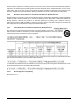
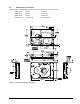

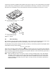
Table Of Contents
- 1.0 Scope 1
- 2.0 Standards, compliance and reference documents 3
- 3.0 General description 7
- 4.0 Performance characteristics 11
- 5.0 Reliability specifications 15
- 6.0 Physical/electrical specifications 23
- 6.1 AC power requirements 23
- 6.2 DC power requirements 23
- 6.3 Power dissipation 29
- 6.4 Environmental limits 32
- 6.4.1 Temperature 32
- 6.4.2 Relative humidity 32
- 6.4.3 Effective altitude (sea level) 33
- 6.4.4 Shock and vibration 33
- 6.4.5 Acoustics 35
- 6.4.6 Air cleanliness 35
- 6.4.7 Corrosive environment 35
- 6.4.8 European Union Restriction of Hazardous Substances (RoHS) Directive 36
- 6.4.9 China Restriction of Hazardous Substances (RoHS) Directive 36
- 6.4.10 Electromagnetic susceptibility 36
- 6.5 Mechanical specifications 37
- 7.0 Defect and error management 39
- 8.0 Installation 43
- 9.0 Interface requirements 47
- 9.1 FC-AL features 47
- 9.1.1 Fibre Channel link service frames 47
- 9.1.2 Fibre Channel task management functions 48
- 9.1.3 Fibre Channel task management responses 48
- 9.1.4 Fibre Channel port login 49
- 9.1.5 Fibre Channel port login accept 50
- 9.1.6 Fibre Channel Process Login 50
- 9.1.7 Fibre Channel Process Login Accept 51
- 9.1.8 Fibre Channel fabric login 51
- 9.1.9 Fibre Channel fabric accept login 52
- 9.1.10 Fibre Channel Arbitrated Loop options 53
- 9.2 Dual port support 53
- 9.3 SCSI commands supported 54
- 9.4 Miscellaneous operating features and conditions 63
- 9.5 FC-AL physical interface 64
- 9.5.1 Physical characteristics 64
- 9.5.2 Connector requirements 65
- 9.5.3 Electrical description 65
- 9.5.4 Pin descriptions 65
- 9.5.5 FC-AL transmitters and receivers 66
- 9.5.6 Power 67
- 9.5.7 Fault LED Out 67
- 9.5.8 Active LED Out 68
- 9.5.9 Enable port bypass signals 68
- 9.5.10 Motor start controls 68
- 9.5.11 SEL_6 through SEL_0 ID lines 69
- 9.5.12 Device control codes 71
- 9.6 Signal characteristics 71
- 9.1 FC-AL features 47
- 10.0 Seagate Technology support services 75
- 1.0 Scope
- 2.0 Standards, compliance and reference documents
- 3.0 General description
- 4.0 Performance characteristics
- 5.0 Reliability specifications
- 6.0 Physical/electrical specifications
- 6.1 AC power requirements
- 6.2 DC power requirements
- 6.3 Power dissipation
- 6.4 Environmental limits
- 6.4.1 Temperature
- 6.4.2 Relative humidity
- 6.4.3 Effective altitude (sea level)
- 6.4.4 Shock and vibration
- 6.4.5 Acoustics
- 6.4.6 Air cleanliness
- 6.4.7 Corrosive environment
- 6.4.8 European Union Restriction of Hazardous Substances (RoHS) Directive
- 6.4.9 China Restriction of Hazardous Substances (RoHS) Directive
- 6.4.10 Electromagnetic susceptibility
- 6.5 Mechanical specifications
- 7.0 Defect and error management
- 8.0 Installation
- 9.0 Interface requirements
- 9.1 FC-AL features
- 9.1.1 Fibre Channel link service frames
- 9.1.2 Fibre Channel task management functions
- 9.1.3 Fibre Channel task management responses
- 9.1.4 Fibre Channel port login
- 9.1.5 Fibre Channel port login accept
- 9.1.6 Fibre Channel Process Login
- 9.1.7 Fibre Channel Process Login Accept
- 9.1.8 Fibre Channel fabric login
- 9.1.9 Fibre Channel fabric accept login
- 9.1.10 Fibre Channel Arbitrated Loop options
- 9.2 Dual port support
- 9.3 SCSI commands supported
- 9.4 Miscellaneous operating features and conditions
- 9.5 FC-AL physical interface
- 9.5.1 Physical characteristics
- 9.5.2 Connector requirements
- 9.5.3 Electrical description
- 9.5.4 Pin descriptions
- 9.5.5 FC-AL transmitters and receivers
- 9.5.6 Power
- 9.5.7 Fault LED Out
- 9.5.8 Active LED Out
- 9.5.9 Enable port bypass signals
- 9.5.10 Motor start controls
- 9.5.11 SEL_6 through SEL_0 ID lines
- 9.5.12 Device control codes
- 9.6 Signal characteristics
- 9.1 FC-AL features
- 10.0 Seagate Technology support services

Cheetah NS 10K.2 FC Product Manual, Rev. B 43
8.0 Installation
Cheetah NS 10K.2 FC disk drive installation is a plug-and-play process. There are no jumpers, switches, or
terminators on the drive. Simply plug the drive into the host’s 40-pin Fibre Channel backpanel connector (FC-
SCA)
—no cables are required. See Section 9.5 for additional information about this connector.
Use the FC-AL interface to select drive ID and all option configurations for devices on the loop.
If multiple devices are on the same FC-AL and physical addresses are used, set the device selection IDs (SEL
IDs) on the backpanel so that no two devices have the same selection ID. This is called the hard assigned arbi-
trated loop physical address (AL_PA). There are 125 AL_PAs available (see Table 26). If you set the AL_PA on
the backpanel to any value other than 0, the device plugged into the backpanel’s SCA connector inherits this
AL_PA. In the event you don’t successfully assign unique hard addresses (and therefore have duplicate selec-
tion IDs assigned to two or more devices), the FC-AL generates a message indicating this condition. If you set
the AL_PA on the backpanel to a value of 0, the system issues a unique soft-assigned physical address auto-
matically.
Loop initialization is the process used to verify or obtain an address. The loop initialization process is per-
formed when power is applied to the drive, when a device is added or removed from the Fibre Channel loop, or
when a device times out attempting to win arbitration.
• Set all option selections in the connector prior to applying power to the drive. If you change options after
applying power to the drive, recycle the drive power to activate the new settings.
• It is not necessary to low-level format this drive. The drive is shipped from the factory low-level formatted in
512-byte logical blocks. You need to reformat the drive only if you want to select a different logical block size.
8.1 Drive ID/option selection
All drive options are made through the interface connector (J1). Table 23 provides the pin descriptions for the
40-pin Fibre Channel single connector (J1).
8.2 Drive orientation
The drive may be mounted in any orientation. All drive performance characterizations, however, have been
done with the drive in horizontal (disks level) and vertical (drive on its side) orientations, which are the two pre-
ferred mounting orientations.
8.3 Cooling
The host enclosure must dissipate heat from the drive. You should confirm that the host enclosure is designed
to ensure that the drive operates within the temperature measurement guidelines described in Section 6.4.1. In
some cases, forced airflow may be required to keep temperatures at or below the temperatures specified in
Section 6.4.1.