
Computer Drive User Manual

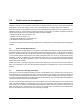
Table Of Contents
- 1.0 Scope 1
- 2.0 Standards, compliance and reference documents 3
- 3.0 General description 7
- 4.0 Performance characteristics 11
- 5.0 Reliability specifications 15
- 6.0 Physical/electrical specifications 23
- 6.1 AC power requirements 23
- 6.2 DC power requirements 23
- 6.3 Power dissipation 29
- 6.4 Environmental limits 32
- 6.4.1 Temperature 32
- 6.4.2 Relative humidity 32
- 6.4.3 Effective altitude (sea level) 33
- 6.4.4 Shock and vibration 33
- 6.4.5 Acoustics 35
- 6.4.6 Air cleanliness 35
- 6.4.7 Corrosive environment 35
- 6.4.8 European Union Restriction of Hazardous Substances (RoHS) Directive 36
- 6.4.9 China Restriction of Hazardous Substances (RoHS) Directive 36
- 6.4.10 Electromagnetic susceptibility 36
- 6.5 Mechanical specifications 37
- 7.0 Defect and error management 39
- 8.0 Installation 43
- 9.0 Interface requirements 47
- 9.1 FC-AL features 47
- 9.1.1 Fibre Channel link service frames 47
- 9.1.2 Fibre Channel task management functions 48
- 9.1.3 Fibre Channel task management responses 48
- 9.1.4 Fibre Channel port login 49
- 9.1.5 Fibre Channel port login accept 50
- 9.1.6 Fibre Channel Process Login 50
- 9.1.7 Fibre Channel Process Login Accept 51
- 9.1.8 Fibre Channel fabric login 51
- 9.1.9 Fibre Channel fabric accept login 52
- 9.1.10 Fibre Channel Arbitrated Loop options 53
- 9.2 Dual port support 53
- 9.3 SCSI commands supported 54
- 9.4 Miscellaneous operating features and conditions 63
- 9.5 FC-AL physical interface 64
- 9.5.1 Physical characteristics 64
- 9.5.2 Connector requirements 65
- 9.5.3 Electrical description 65
- 9.5.4 Pin descriptions 65
- 9.5.5 FC-AL transmitters and receivers 66
- 9.5.6 Power 67
- 9.5.7 Fault LED Out 67
- 9.5.8 Active LED Out 68
- 9.5.9 Enable port bypass signals 68
- 9.5.10 Motor start controls 68
- 9.5.11 SEL_6 through SEL_0 ID lines 69
- 9.5.12 Device control codes 71
- 9.6 Signal characteristics 71
- 9.1 FC-AL features 47
- 10.0 Seagate Technology support services 75
- 1.0 Scope
- 2.0 Standards, compliance and reference documents
- 3.0 General description
- 4.0 Performance characteristics
- 5.0 Reliability specifications
- 6.0 Physical/electrical specifications
- 6.1 AC power requirements
- 6.2 DC power requirements
- 6.3 Power dissipation
- 6.4 Environmental limits
- 6.4.1 Temperature
- 6.4.2 Relative humidity
- 6.4.3 Effective altitude (sea level)
- 6.4.4 Shock and vibration
- 6.4.5 Acoustics
- 6.4.6 Air cleanliness
- 6.4.7 Corrosive environment
- 6.4.8 European Union Restriction of Hazardous Substances (RoHS) Directive
- 6.4.9 China Restriction of Hazardous Substances (RoHS) Directive
- 6.4.10 Electromagnetic susceptibility
- 6.5 Mechanical specifications
- 7.0 Defect and error management
- 8.0 Installation
- 9.0 Interface requirements
- 9.1 FC-AL features
- 9.1.1 Fibre Channel link service frames
- 9.1.2 Fibre Channel task management functions
- 9.1.3 Fibre Channel task management responses
- 9.1.4 Fibre Channel port login
- 9.1.5 Fibre Channel port login accept
- 9.1.6 Fibre Channel Process Login
- 9.1.7 Fibre Channel Process Login Accept
- 9.1.8 Fibre Channel fabric login
- 9.1.9 Fibre Channel fabric accept login
- 9.1.10 Fibre Channel Arbitrated Loop options
- 9.2 Dual port support
- 9.3 SCSI commands supported
- 9.4 Miscellaneous operating features and conditions
- 9.5 FC-AL physical interface
- 9.5.1 Physical characteristics
- 9.5.2 Connector requirements
- 9.5.3 Electrical description
- 9.5.4 Pin descriptions
- 9.5.5 FC-AL transmitters and receivers
- 9.5.6 Power
- 9.5.7 Fault LED Out
- 9.5.8 Active LED Out
- 9.5.9 Enable port bypass signals
- 9.5.10 Motor start controls
- 9.5.11 SEL_6 through SEL_0 ID lines
- 9.5.12 Device control codes
- 9.6 Signal characteristics
- 9.1 FC-AL features
- 10.0 Seagate Technology support services

Cheetah NS 10K.2 FC Product Manual, Rev. B 41
7.3 FC-AL system errors
Information on the reporting of operational errors or faults across the interface is given in the Fibre Channel
Interface Manual. The FCP Response returns information to the host about numerous kinds of errors or faults.
The Receive Diagnostic Results reports the results of diagnostic operations performed by the drive.
Status returned by the drive to the initiator is described in the Fibre Channel Interface Manual. Status reporting
plays a role in systems error management and its use in that respect is described in sections where the various
commands are discussed.
7.4 Background Media Scan
Background Media Scan (BMS) is a self-initiated media scan. BMS is defined in the T10 document SPC-4
available from the T10 committee. BMS performs sequential reads across the entire pack of the media while
the drive is idle. In RAID arrays, BMS allows hot spare drives to be scanned for defects prior to being put into
service by the host system. On regular duty drives, if the host system makes use of the BMS Log Page, it can
avoid placing data in suspect locations on the media. Unreadable and recovered error sites will be logged or
reallocated per ARRE/AWRE settings.
With BMS, the host system can consume less power and system overhead by only checking BMS status and
results rather than tying up the bus and consuming power in the process of host-initiated media scanning activ-
ity.
Since the background scan functions are only done during idle periods, BMS causes a negligible impact to sys-
tem performance. The first BMS scan for a newly manufactured drive is performed as quickly as possible to
verify the media and protect data by setting the “Start time after idle” to 5ms, all subsequent scans begin after
500ms of idle time. Other features that normally use idle time to function will function normally because BMS
functions for bursts of 800ms and then suspends activity for 100ms to allow other background functions to
operate.
BMS interrupts immediately to service host commands from the interface bus while performing reads. BMS will
complete any BMS-initiated error recovery prior to returning to service host-initiated commands. Overhead
associated with a return to host-servicing activity from BMS only impacts the first command that interrupted
BMS, this results in a typical delay of about 1 ms.
7.5 Media Pre-Scan
Media Pre-Scan is a feature that allows the drive to repair media errors that would otherwise have been found
by the host system during critical data accesses early in the drive’s life. The default setting for Media Pre-Scan
is enabled on standard products. Media Pre-Scan checks each write command to determine if the destination
LBAs have been scanned by BMS. If the LBAs have been verified, the drive proceeds with the normal write
command. If the LBAs have not been verified by BMS, Pre-Scan will convert the write to a write verify to certify
that the data was properly written to the disk.
Note. During Pre-Scan write verify commands, write performance may decrease by 50% until Pre-Scan
completes. Write performance testing should be performed after Pre-Scan is complete. This may
be checked by reading the BMS status.
To expedite the scan of the full pack and subsequently exit from the Pre-Scan period, BMS will begin scanning
immediately when the drive goes to idle during the Pre-Scan period. In the event that the drive is in a high
transaction traffic environment and is unable to complete a BMS scan within 24 power on hours BMS will dis-
able Pre-Scan to restore full performance to the system.