
Computer Drive User Manual
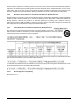
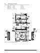

Table Of Contents
- 1.0 Scope 1
- 2.0 Standards, compliance and reference documents 3
- 3.0 General description 7
- 4.0 Performance characteristics 11
- 5.0 Reliability specifications 15
- 6.0 Physical/electrical specifications 23
- 6.1 AC power requirements 23
- 6.2 DC power requirements 23
- 6.3 Power dissipation 29
- 6.4 Environmental limits 32
- 6.4.1 Temperature 32
- 6.4.2 Relative humidity 32
- 6.4.3 Effective altitude (sea level) 33
- 6.4.4 Shock and vibration 33
- 6.4.5 Acoustics 35
- 6.4.6 Air cleanliness 35
- 6.4.7 Corrosive environment 35
- 6.4.8 European Union Restriction of Hazardous Substances (RoHS) Directive 36
- 6.4.9 China Restriction of Hazardous Substances (RoHS) Directive 36
- 6.4.10 Electromagnetic susceptibility 36
- 6.5 Mechanical specifications 37
- 7.0 Defect and error management 39
- 8.0 Installation 43
- 9.0 Interface requirements 47
- 9.1 FC-AL features 47
- 9.1.1 Fibre Channel link service frames 47
- 9.1.2 Fibre Channel task management functions 48
- 9.1.3 Fibre Channel task management responses 48
- 9.1.4 Fibre Channel port login 49
- 9.1.5 Fibre Channel port login accept 50
- 9.1.6 Fibre Channel Process Login 50
- 9.1.7 Fibre Channel Process Login Accept 51
- 9.1.8 Fibre Channel fabric login 51
- 9.1.9 Fibre Channel fabric accept login 52
- 9.1.10 Fibre Channel Arbitrated Loop options 53
- 9.2 Dual port support 53
- 9.3 SCSI commands supported 54
- 9.4 Miscellaneous operating features and conditions 63
- 9.5 FC-AL physical interface 64
- 9.5.1 Physical characteristics 64
- 9.5.2 Connector requirements 65
- 9.5.3 Electrical description 65
- 9.5.4 Pin descriptions 65
- 9.5.5 FC-AL transmitters and receivers 66
- 9.5.6 Power 67
- 9.5.7 Fault LED Out 67
- 9.5.8 Active LED Out 68
- 9.5.9 Enable port bypass signals 68
- 9.5.10 Motor start controls 68
- 9.5.11 SEL_6 through SEL_0 ID lines 69
- 9.5.12 Device control codes 71
- 9.6 Signal characteristics 71
- 9.1 FC-AL features 47
- 10.0 Seagate Technology support services 75
- 1.0 Scope
- 2.0 Standards, compliance and reference documents
- 3.0 General description
- 4.0 Performance characteristics
- 5.0 Reliability specifications
- 6.0 Physical/electrical specifications
- 6.1 AC power requirements
- 6.2 DC power requirements
- 6.3 Power dissipation
- 6.4 Environmental limits
- 6.4.1 Temperature
- 6.4.2 Relative humidity
- 6.4.3 Effective altitude (sea level)
- 6.4.4 Shock and vibration
- 6.4.5 Acoustics
- 6.4.6 Air cleanliness
- 6.4.7 Corrosive environment
- 6.4.8 European Union Restriction of Hazardous Substances (RoHS) Directive
- 6.4.9 China Restriction of Hazardous Substances (RoHS) Directive
- 6.4.10 Electromagnetic susceptibility
- 6.5 Mechanical specifications
- 7.0 Defect and error management
- 8.0 Installation
- 9.0 Interface requirements
- 9.1 FC-AL features
- 9.1.1 Fibre Channel link service frames
- 9.1.2 Fibre Channel task management functions
- 9.1.3 Fibre Channel task management responses
- 9.1.4 Fibre Channel port login
- 9.1.5 Fibre Channel port login accept
- 9.1.6 Fibre Channel Process Login
- 9.1.7 Fibre Channel Process Login Accept
- 9.1.8 Fibre Channel fabric login
- 9.1.9 Fibre Channel fabric accept login
- 9.1.10 Fibre Channel Arbitrated Loop options
- 9.2 Dual port support
- 9.3 SCSI commands supported
- 9.4 Miscellaneous operating features and conditions
- 9.5 FC-AL physical interface
- 9.5.1 Physical characteristics
- 9.5.2 Connector requirements
- 9.5.3 Electrical description
- 9.5.4 Pin descriptions
- 9.5.5 FC-AL transmitters and receivers
- 9.5.6 Power
- 9.5.7 Fault LED Out
- 9.5.8 Active LED Out
- 9.5.9 Enable port bypass signals
- 9.5.10 Motor start controls
- 9.5.11 SEL_6 through SEL_0 ID lines
- 9.5.12 Device control codes
- 9.6 Signal characteristics
- 9.1 FC-AL features
- 10.0 Seagate Technology support services

40 Cheetah NS 10K.2 FC Product Manual, Rev. B
The drive firmware error recovery algorithms consists of 11 levels for read recoveries and five levels for write.
Each level may consist of multiple steps, where a step is defined as a recovery function involving a single re-
read or re-write attempt. The maximum level used by the drive in LBA recovery is determined by the read and
write retry counts.
Table 5 equates the read and write retry count with the maximum possible recovery time for read and write
recovery of individual LBAs. The times given do not include time taken to perform reallocations. Reallocations
are performed when the ARRE bit (for reads) or AWRE bit (for writes) is one, the RC bit is zero, and the recov-
ery time limit for the command has not yet been met. Time needed to perform reallocation is not counted
against the recovery time limit.
When the RC bit is one, reallocations are disabled even if the ARRE or AWRE bits are one. The drive will still
perform data recovery actions within the limits defined by the Read Retry Count, Write Retry Count, and
Recovery Time Limit parameters. However, the drive does not report any unrecovered errors.
[1] These values are subject to change.
Setting these retry counts to a value below the default setting could result in an increased unrecovered
error rate which may exceed the value given in this product manual. A setting of zero (0) will result in the
drive not performing error recovery.
For example, suppose the Read/Write Recovery page has the RC bit set to 0, read retry count set to 4,
and the recovery time limit field (Mode Sense page 01, bytes 10 and 11) set to FF FF hex (maximum). A
four LBA Read command is allowed to take up to 442.89 msec recovery time for each of the four LBAs in
the command. If the recovery time limit is set to 00 C8 hex (200 msec decimal) a four LBA read command
is allowed to take up to 200 msec for all error recovery within that command. The use of the Recovery
Time Limit field allows finer granularity on control of the time spent in error recovery. The recovery time
limit only starts counting when the drive is executing error recovery and it restarts on each command.
Therefore, each command’s total recovery time is subject to the recovery time limit. Note: A recovery time
limit of 0 will use the drive’s default value of FF FF. Minimum recovery time limit is achieved by setting the
Recovery Time Limit field to 00 01.
Table 5: Read and write retry count maximum recovery times
Read retry count
1
Maximum recovery time per
LBA (cumulative, msec) Write retry count
1
Maximum recovery time per
LBA (cumulative, msec)
0 77.81 0 35.91
1 89.78 1 53.865
2 305.24 2 83.79
3 347.13 3 101.745
4 442.89 4 179.655
5 490.77 5 (default) 221.55
6 538.65
7 670.32
8 807.98
9 855.86
10 897.75
11 (default) 2370.04