
Computer Drive User Manual
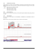
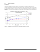
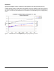
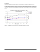
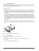
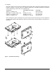
Table Of Contents
- 1.0 Scope 1
- 2.0 Standards, compliance and reference documents 3
- 3.0 General description 7
- 4.0 Performance characteristics 11
- 5.0 Reliability specifications 15
- 6.0 Physical/electrical specifications 23
- 6.1 AC power requirements 23
- 6.2 DC power requirements 23
- 6.3 Power dissipation 29
- 6.4 Environmental limits 32
- 6.4.1 Temperature 32
- 6.4.2 Relative humidity 32
- 6.4.3 Effective altitude (sea level) 33
- 6.4.4 Shock and vibration 33
- 6.4.5 Acoustics 35
- 6.4.6 Air cleanliness 35
- 6.4.7 Corrosive environment 35
- 6.4.8 European Union Restriction of Hazardous Substances (RoHS) Directive 36
- 6.4.9 China Restriction of Hazardous Substances (RoHS) Directive 36
- 6.4.10 Electromagnetic susceptibility 36
- 6.5 Mechanical specifications 37
- 7.0 Defect and error management 39
- 8.0 Installation 43
- 9.0 Interface requirements 47
- 9.1 FC-AL features 47
- 9.1.1 Fibre Channel link service frames 47
- 9.1.2 Fibre Channel task management functions 48
- 9.1.3 Fibre Channel task management responses 48
- 9.1.4 Fibre Channel port login 49
- 9.1.5 Fibre Channel port login accept 50
- 9.1.6 Fibre Channel Process Login 50
- 9.1.7 Fibre Channel Process Login Accept 51
- 9.1.8 Fibre Channel fabric login 51
- 9.1.9 Fibre Channel fabric accept login 52
- 9.1.10 Fibre Channel Arbitrated Loop options 53
- 9.2 Dual port support 53
- 9.3 SCSI commands supported 54
- 9.4 Miscellaneous operating features and conditions 63
- 9.5 FC-AL physical interface 64
- 9.5.1 Physical characteristics 64
- 9.5.2 Connector requirements 65
- 9.5.3 Electrical description 65
- 9.5.4 Pin descriptions 65
- 9.5.5 FC-AL transmitters and receivers 66
- 9.5.6 Power 67
- 9.5.7 Fault LED Out 67
- 9.5.8 Active LED Out 68
- 9.5.9 Enable port bypass signals 68
- 9.5.10 Motor start controls 68
- 9.5.11 SEL_6 through SEL_0 ID lines 69
- 9.5.12 Device control codes 71
- 9.6 Signal characteristics 71
- 9.1 FC-AL features 47
- 10.0 Seagate Technology support services 75
- 1.0 Scope
- 2.0 Standards, compliance and reference documents
- 3.0 General description
- 4.0 Performance characteristics
- 5.0 Reliability specifications
- 6.0 Physical/electrical specifications
- 6.1 AC power requirements
- 6.2 DC power requirements
- 6.3 Power dissipation
- 6.4 Environmental limits
- 6.4.1 Temperature
- 6.4.2 Relative humidity
- 6.4.3 Effective altitude (sea level)
- 6.4.4 Shock and vibration
- 6.4.5 Acoustics
- 6.4.6 Air cleanliness
- 6.4.7 Corrosive environment
- 6.4.8 European Union Restriction of Hazardous Substances (RoHS) Directive
- 6.4.9 China Restriction of Hazardous Substances (RoHS) Directive
- 6.4.10 Electromagnetic susceptibility
- 6.5 Mechanical specifications
- 7.0 Defect and error management
- 8.0 Installation
- 9.0 Interface requirements
- 9.1 FC-AL features
- 9.1.1 Fibre Channel link service frames
- 9.1.2 Fibre Channel task management functions
- 9.1.3 Fibre Channel task management responses
- 9.1.4 Fibre Channel port login
- 9.1.5 Fibre Channel port login accept
- 9.1.6 Fibre Channel Process Login
- 9.1.7 Fibre Channel Process Login Accept
- 9.1.8 Fibre Channel fabric login
- 9.1.9 Fibre Channel fabric accept login
- 9.1.10 Fibre Channel Arbitrated Loop options
- 9.2 Dual port support
- 9.3 SCSI commands supported
- 9.4 Miscellaneous operating features and conditions
- 9.5 FC-AL physical interface
- 9.5.1 Physical characteristics
- 9.5.2 Connector requirements
- 9.5.3 Electrical description
- 9.5.4 Pin descriptions
- 9.5.5 FC-AL transmitters and receivers
- 9.5.6 Power
- 9.5.7 Fault LED Out
- 9.5.8 Active LED Out
- 9.5.9 Enable port bypass signals
- 9.5.10 Motor start controls
- 9.5.11 SEL_6 through SEL_0 ID lines
- 9.5.12 Device control codes
- 9.6 Signal characteristics
- 9.1 FC-AL features
- 10.0 Seagate Technology support services

Cheetah NS 10K.2 FC Product Manual, Rev. B 33
6.4.3 Effective altitude (sea level)
a. Operating
–1,000 to +10,000 feet (–305 to +3,048 meters)
b. Non-operating
–1,000 to +40,000 feet (–305 to +12,192 meters)
6.4.4 Shock and vibration
Shock and vibration limits specified in this document are measured directly on the drive chassis. If the drive is
installed in an enclosure to which the stated shock and/or vibration criteria is applied, resonances may occur
internally to the enclosure resulting in drive movement in excess of the stated limits. If this situation is apparent,
it may be necessary to modify the enclosure to minimize drive movement.
The limits of shock and vibration defined within this document are specified with the drive mounted by any of
the four methods shown in Figure 8, and in accordance with the restrictions of Section 8.4.
6.4.4.1 Shock
a. Operating—normal
The drive, as installed for normal operation, shall operate error free while subjected to intermittent shock not
exceeding:
• 15 Gs at a duration of 11 msec (half sinewave)
• 20 Gs at a duration of 2 msec (half sinewave)
• 60 Gs at a duration of 2 msec (half sinewave) when performing reads only
Shock may be applied in the X, Y, or Z axis. Shock is not to be repeated more than once every 2 seconds.
b. Operating—abnormal
Equipment, as installed for normal operation, does not incur physical damage while subjected to intermit-
tent shock not exceeding 40 Gs at a duration of 11 msec (half sinewave). Shock occurring at abnormal lev-
els may promote degraded operational performance during the abnormal shock period. Specified
operational performance will continue when normal operating shock levels resume. Shock may be applied
in the X, Y, or Z axis. Shock is not to be repeated more than once every 2 seconds.
c. Non-operating
The limits of non-operating shock shall apply to all conditions of handling and transportation. This includes
both isolated drives and integrated drives.
The drive subjected to nonrepetitive shock not exceeding the three values below, shall not exhibit device
damage or performance degradation.
• 80 Gs at a duration of 11 msec (half sinewave)
• 300 Gs at a duration of 2 msec (half sinewave)
• 150 Gs at a duration of 0.5 msec (half sinewave)
Shock may be applied in the X, Y, or Z axis.