
Computer Drive User Manual
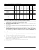
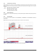
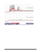
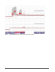
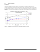
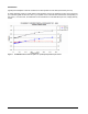
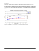
Table Of Contents
- 1.0 Scope 1
- 2.0 Standards, compliance and reference documents 3
- 3.0 General description 7
- 4.0 Performance characteristics 11
- 5.0 Reliability specifications 15
- 6.0 Physical/electrical specifications 23
- 6.1 AC power requirements 23
- 6.2 DC power requirements 23
- 6.3 Power dissipation 29
- 6.4 Environmental limits 32
- 6.4.1 Temperature 32
- 6.4.2 Relative humidity 32
- 6.4.3 Effective altitude (sea level) 33
- 6.4.4 Shock and vibration 33
- 6.4.5 Acoustics 35
- 6.4.6 Air cleanliness 35
- 6.4.7 Corrosive environment 35
- 6.4.8 European Union Restriction of Hazardous Substances (RoHS) Directive 36
- 6.4.9 China Restriction of Hazardous Substances (RoHS) Directive 36
- 6.4.10 Electromagnetic susceptibility 36
- 6.5 Mechanical specifications 37
- 7.0 Defect and error management 39
- 8.0 Installation 43
- 9.0 Interface requirements 47
- 9.1 FC-AL features 47
- 9.1.1 Fibre Channel link service frames 47
- 9.1.2 Fibre Channel task management functions 48
- 9.1.3 Fibre Channel task management responses 48
- 9.1.4 Fibre Channel port login 49
- 9.1.5 Fibre Channel port login accept 50
- 9.1.6 Fibre Channel Process Login 50
- 9.1.7 Fibre Channel Process Login Accept 51
- 9.1.8 Fibre Channel fabric login 51
- 9.1.9 Fibre Channel fabric accept login 52
- 9.1.10 Fibre Channel Arbitrated Loop options 53
- 9.2 Dual port support 53
- 9.3 SCSI commands supported 54
- 9.4 Miscellaneous operating features and conditions 63
- 9.5 FC-AL physical interface 64
- 9.5.1 Physical characteristics 64
- 9.5.2 Connector requirements 65
- 9.5.3 Electrical description 65
- 9.5.4 Pin descriptions 65
- 9.5.5 FC-AL transmitters and receivers 66
- 9.5.6 Power 67
- 9.5.7 Fault LED Out 67
- 9.5.8 Active LED Out 68
- 9.5.9 Enable port bypass signals 68
- 9.5.10 Motor start controls 68
- 9.5.11 SEL_6 through SEL_0 ID lines 69
- 9.5.12 Device control codes 71
- 9.6 Signal characteristics 71
- 9.1 FC-AL features 47
- 10.0 Seagate Technology support services 75
- 1.0 Scope
- 2.0 Standards, compliance and reference documents
- 3.0 General description
- 4.0 Performance characteristics
- 5.0 Reliability specifications
- 6.0 Physical/electrical specifications
- 6.1 AC power requirements
- 6.2 DC power requirements
- 6.3 Power dissipation
- 6.4 Environmental limits
- 6.4.1 Temperature
- 6.4.2 Relative humidity
- 6.4.3 Effective altitude (sea level)
- 6.4.4 Shock and vibration
- 6.4.5 Acoustics
- 6.4.6 Air cleanliness
- 6.4.7 Corrosive environment
- 6.4.8 European Union Restriction of Hazardous Substances (RoHS) Directive
- 6.4.9 China Restriction of Hazardous Substances (RoHS) Directive
- 6.4.10 Electromagnetic susceptibility
- 6.5 Mechanical specifications
- 7.0 Defect and error management
- 8.0 Installation
- 9.0 Interface requirements
- 9.1 FC-AL features
- 9.1.1 Fibre Channel link service frames
- 9.1.2 Fibre Channel task management functions
- 9.1.3 Fibre Channel task management responses
- 9.1.4 Fibre Channel port login
- 9.1.5 Fibre Channel port login accept
- 9.1.6 Fibre Channel Process Login
- 9.1.7 Fibre Channel Process Login Accept
- 9.1.8 Fibre Channel fabric login
- 9.1.9 Fibre Channel fabric accept login
- 9.1.10 Fibre Channel Arbitrated Loop options
- 9.2 Dual port support
- 9.3 SCSI commands supported
- 9.4 Miscellaneous operating features and conditions
- 9.5 FC-AL physical interface
- 9.5.1 Physical characteristics
- 9.5.2 Connector requirements
- 9.5.3 Electrical description
- 9.5.4 Pin descriptions
- 9.5.5 FC-AL transmitters and receivers
- 9.5.6 Power
- 9.5.7 Fault LED Out
- 9.5.8 Active LED Out
- 9.5.9 Enable port bypass signals
- 9.5.10 Motor start controls
- 9.5.11 SEL_6 through SEL_0 ID lines
- 9.5.12 Device control codes
- 9.6 Signal characteristics
- 9.1 FC-AL features
- 10.0 Seagate Technology support services
26 Cheetah NS 10K.2 FC Product Manual, Rev. B
6.2.1 Conducted noise immunity
Noise is specified as a periodic and random distribution
of frequencies covering a band from DC to 10 MHz.
Maximum allowed noise values given below are peak-to-peak measurements and apply at the drive power
connector.
6.2.2 Power sequencing
The drive does not require power sequencing. The drive p
rotects against inadvertent writing during power-up
and down.
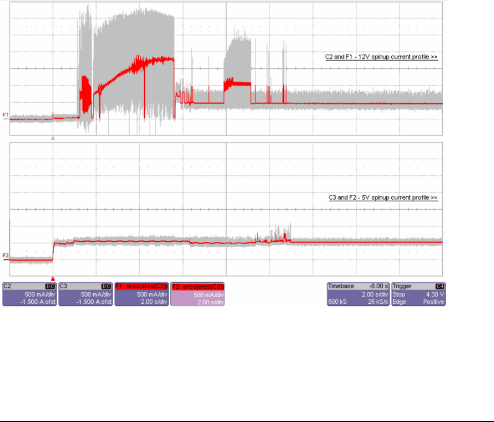
6.2.3 Current profiles
The +12V and +5V current profiles for the ST360000
2FC, ST3450802FC and ST3300602FC models are
shown below.
Note: All times and currents are typical. See Tables 2 and 3 for maximum current requirements.
Figure 1. Typical ST3600002FC drive, 4
Gbit, +5V and +12V current profiles
+5 V = 250 mV pp from 0 to 100 kHz to 20 MHz.
+12 V = 800 mV pp from 100 Hz to 8 KHz.
450 mV pp from 8 KHz to 20 KHz.
250 mV pp from 20 KHz to 5 MHz.